Ambercycle
At Ambercycle I worked as the lead engineer to create systems and processes from the ground up.
Machine Shop
After we acquired a new space one of my first big projects was to design a lab space and a machine shop.
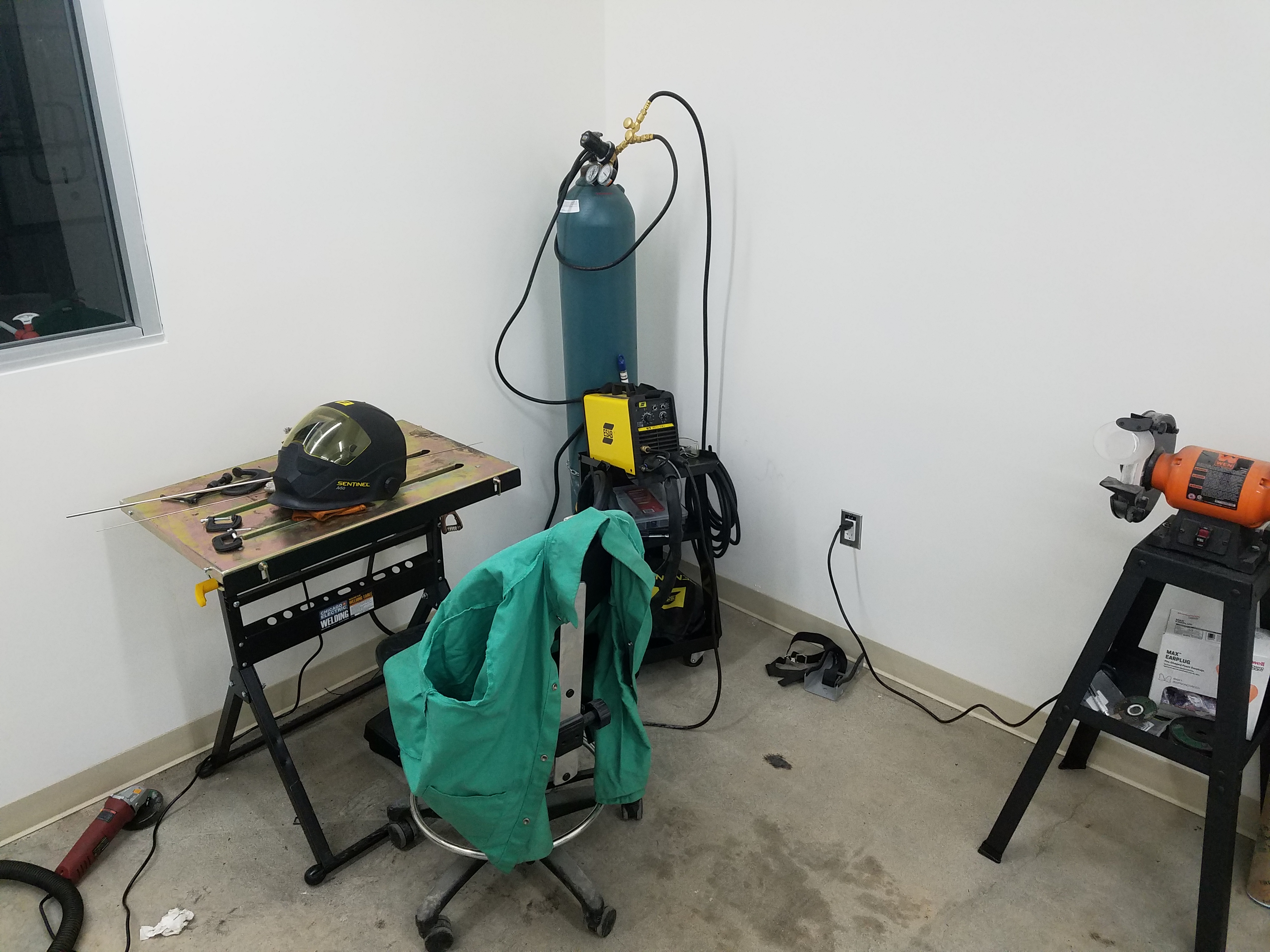
I wanted a TIG welder with HF starting so I could weld Stainless Steel. I was well pleased with this 205A ESAB, I also added a gas lense kit to the torch and a splitter purge the backside of thin stainless parts.
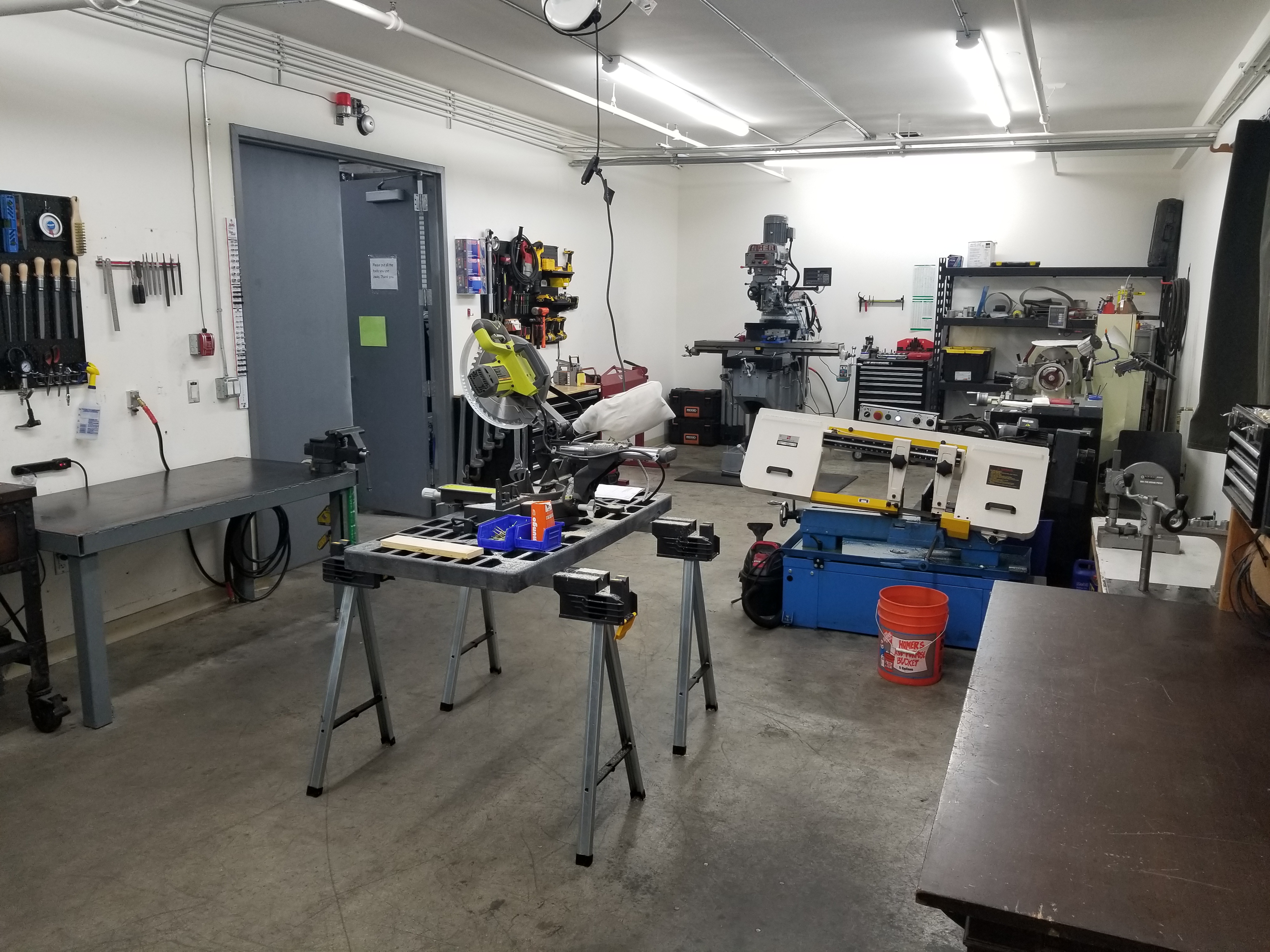
The Bandsaw was another good find, it was a fixed base miter so the saw itself pivoted which meant I didn't have to try clamping at an angle.
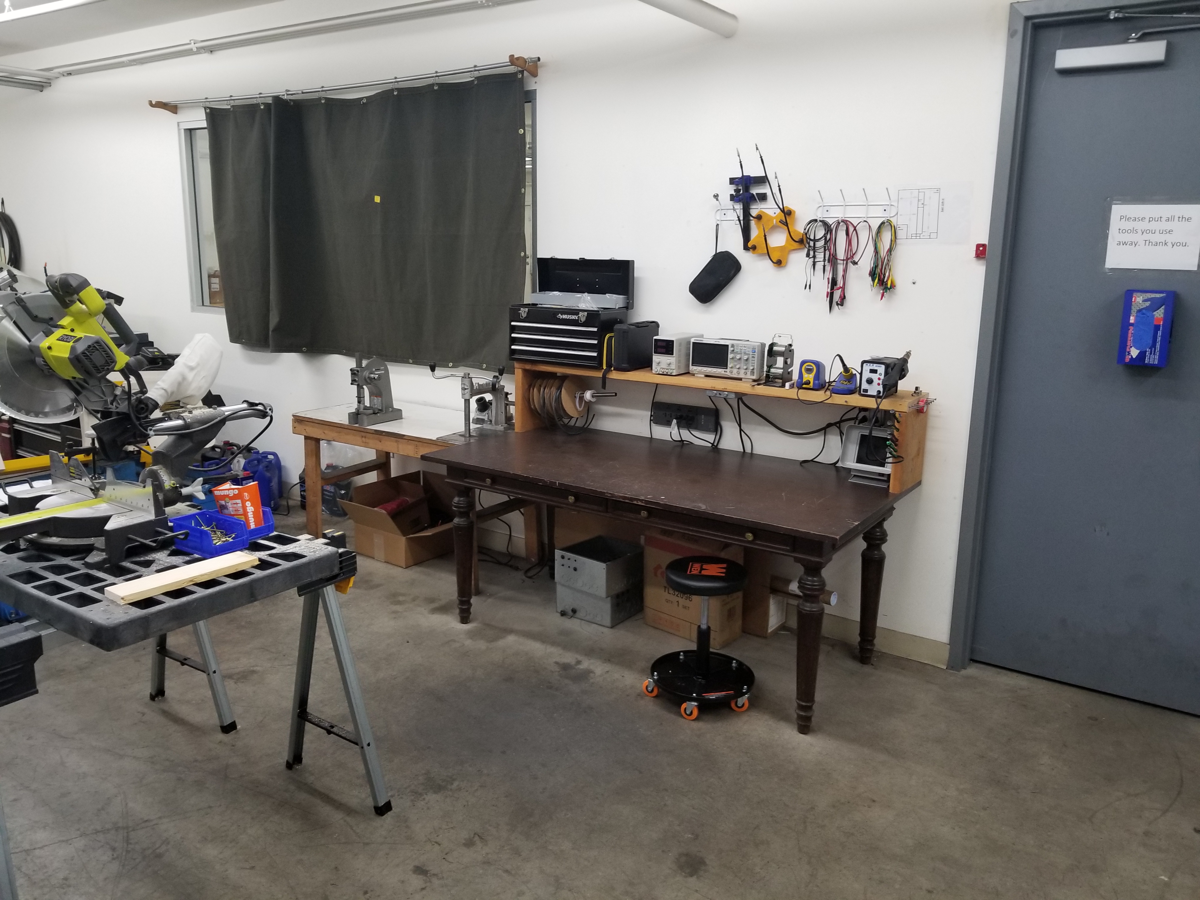
Soldering, and testing equipment was a must, the oscilloscope was especially useful when testing flowmeters and signal devices.
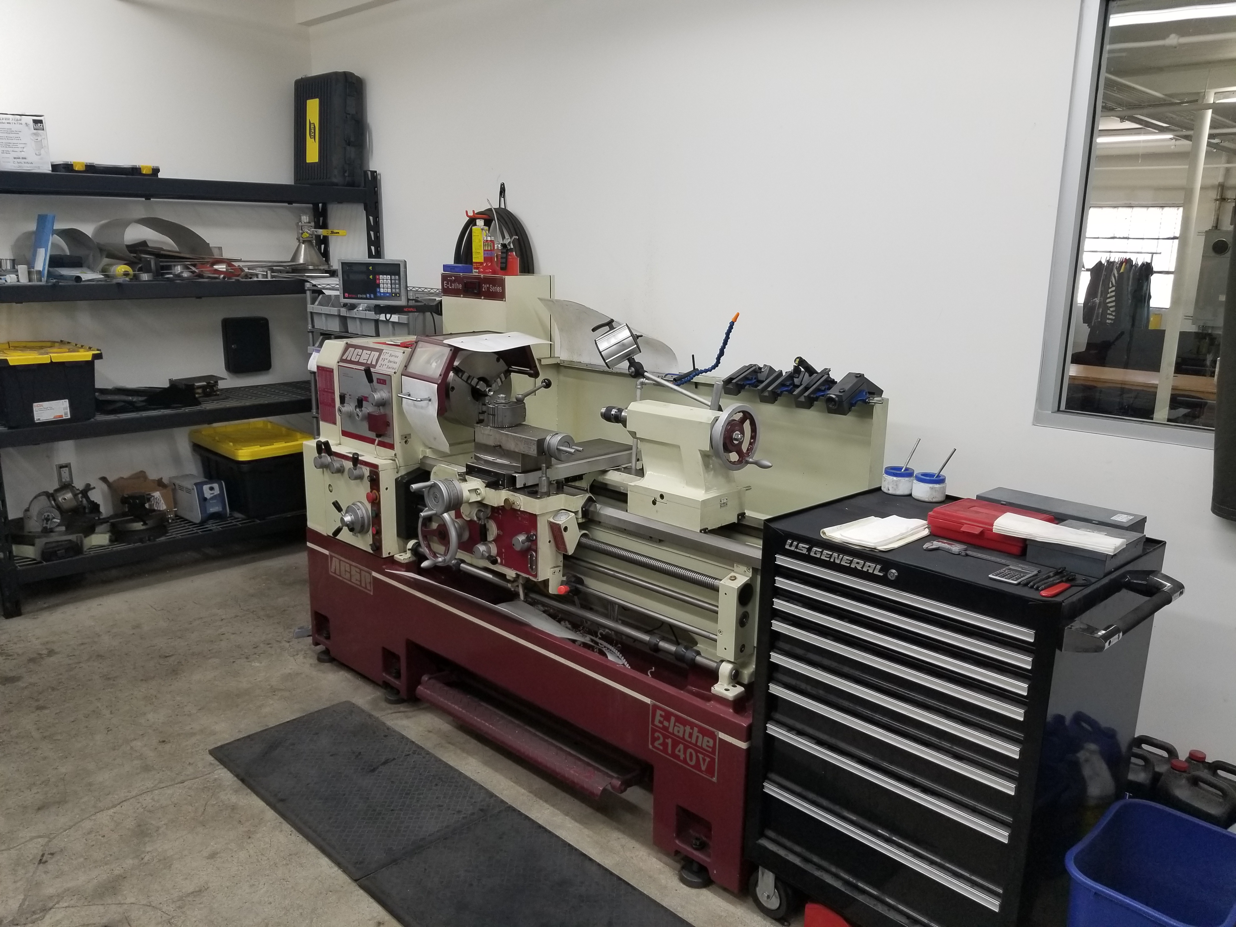
ACER makes a very nice lathe with a large VFD driven motor. This model had and XZ DRO with Constant Surface Speed, and a 3in spindle bore. I chose a multifix tool post and it performed very well. I used this lathe almost every day.
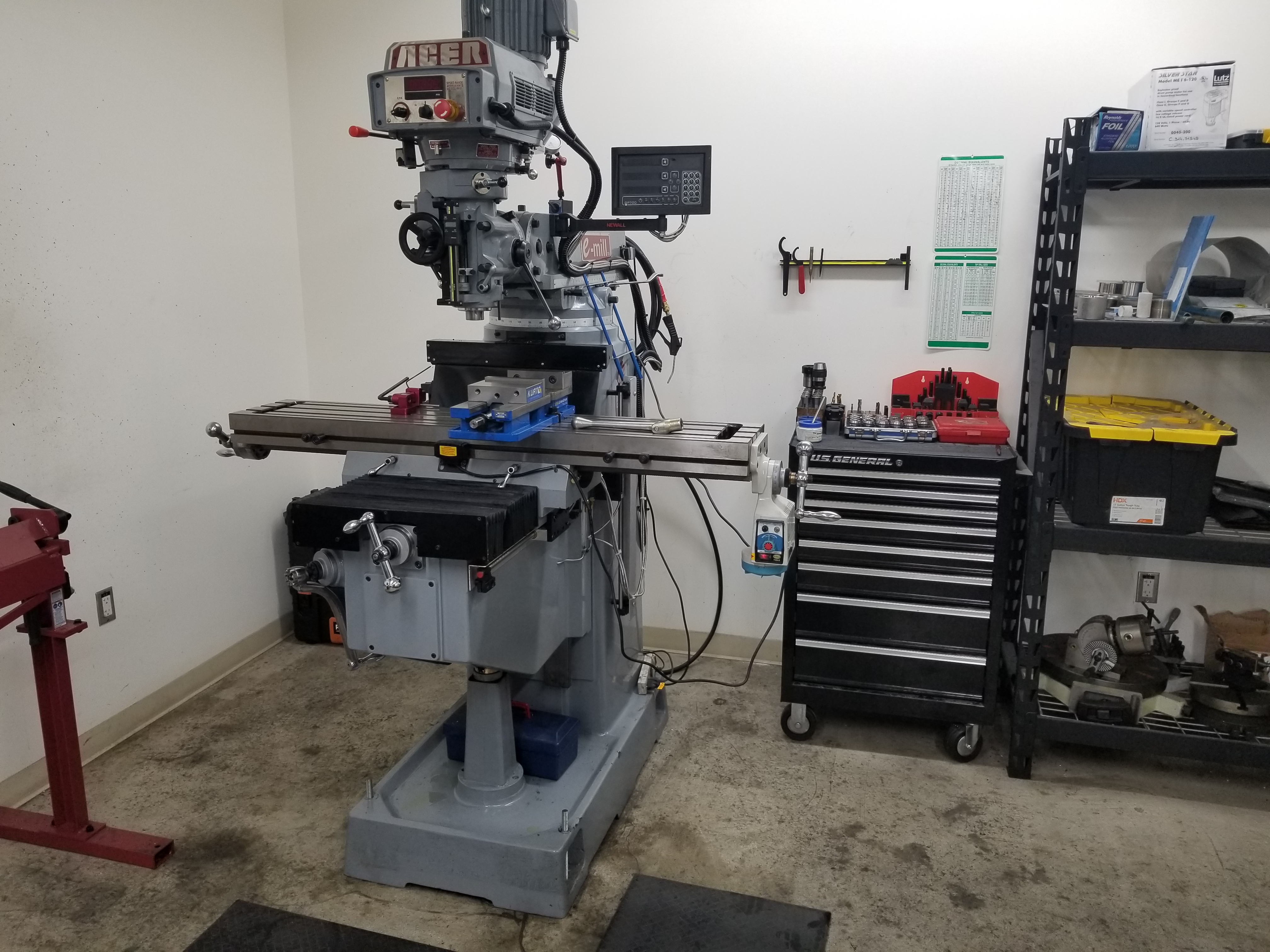
The Mill was also and ACER and had a similar VFD drive, it had an XY and Knee DRO and a Quill Kit. I chose a bigger model with box ways for more rigidity. The size allowed me to work with taller pieces.
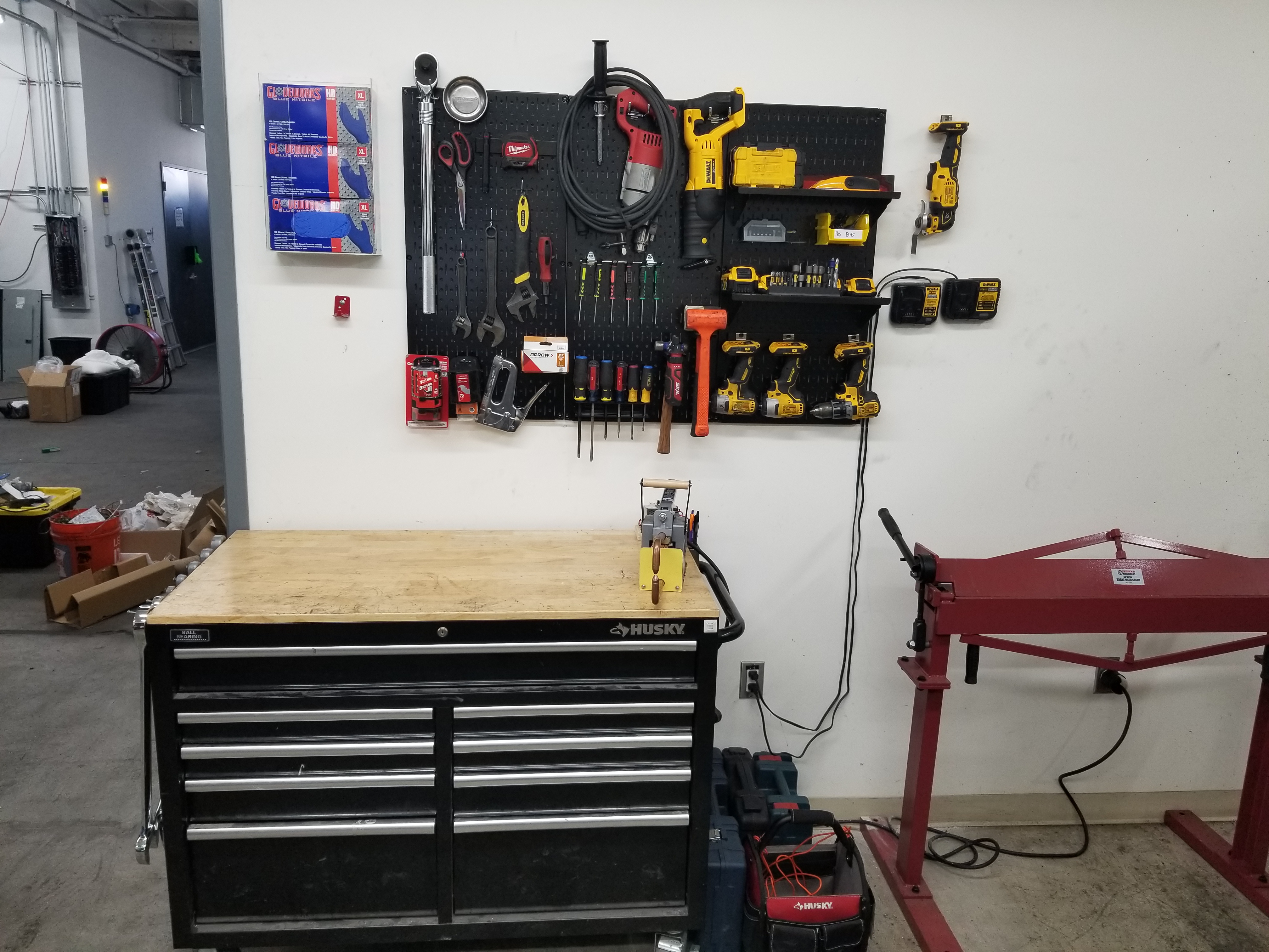
Our tools quickly multiplied despite the machine shop staying the same size. Organization was key to keeping everything running smoothly.
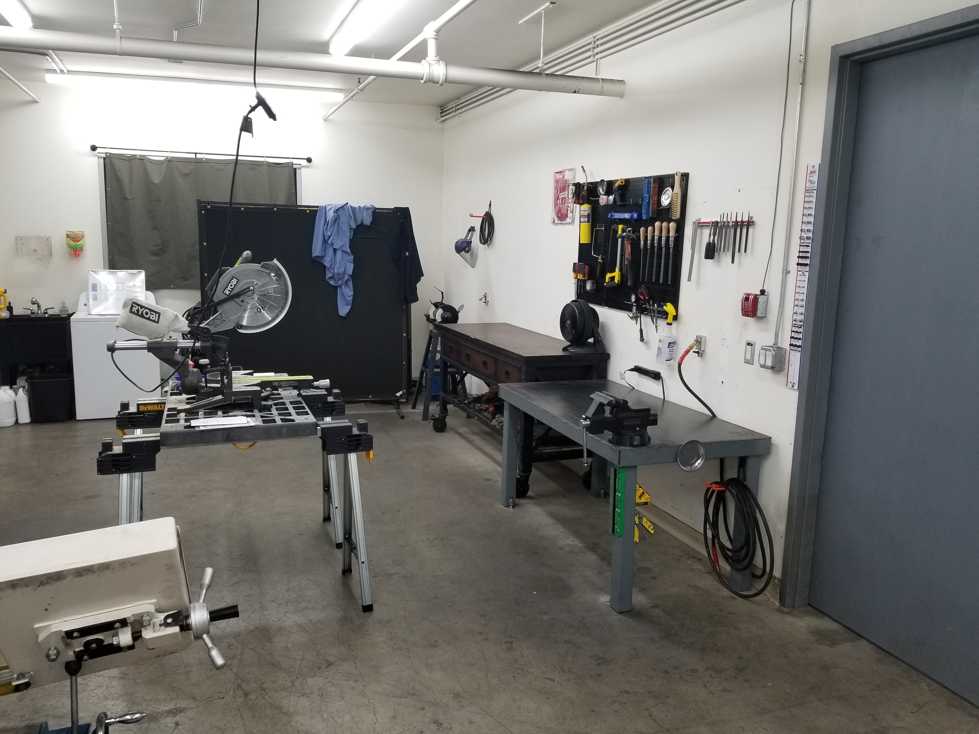
This heavy steel workbench was perfect for assembling and tearing down equipment.
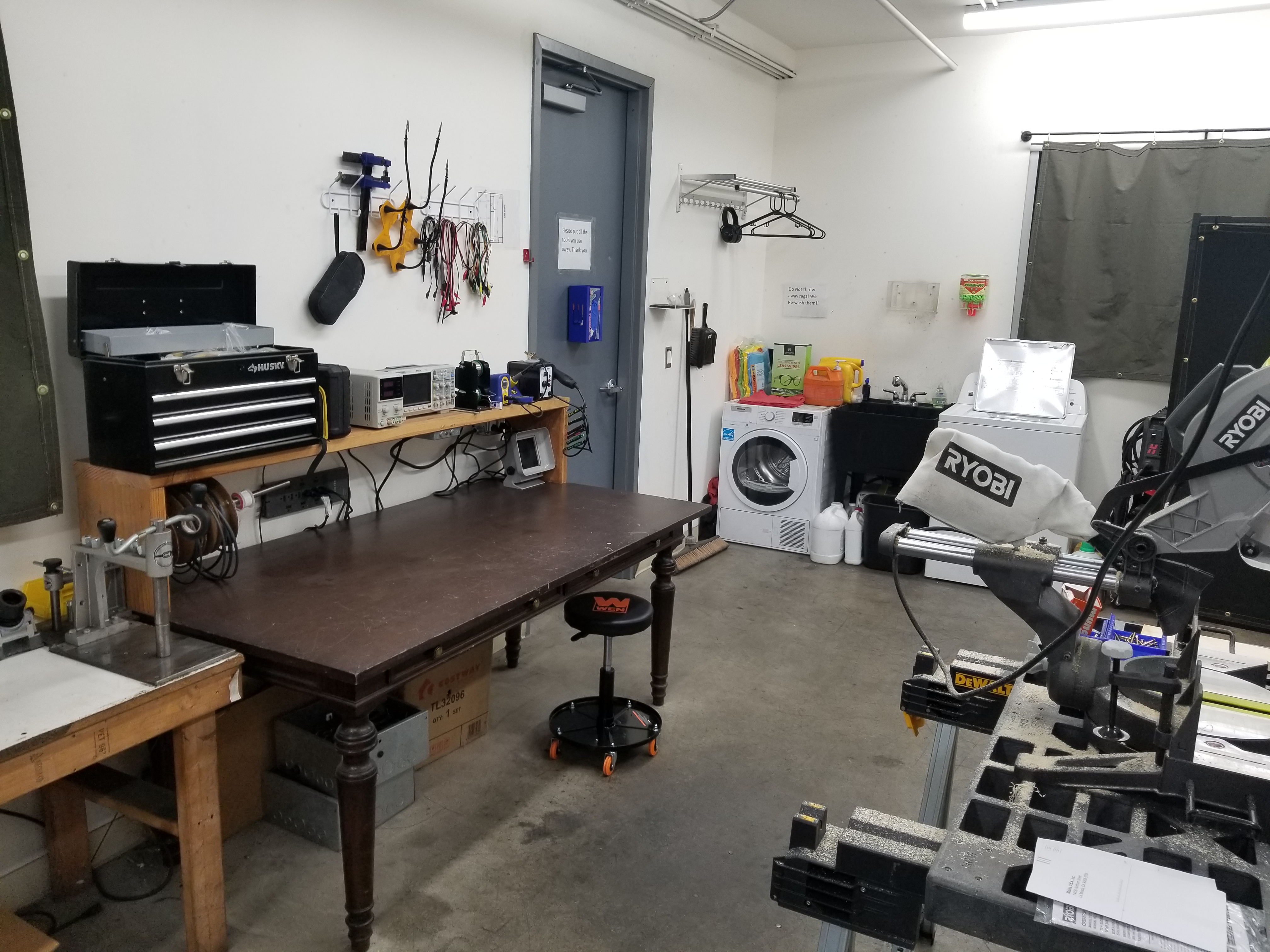
Welding machining and grinding soil clothing quickly, so I incorporated a washer and dryer into the lab so we could regularly wash our PPE.
Lab-Scale Reactors
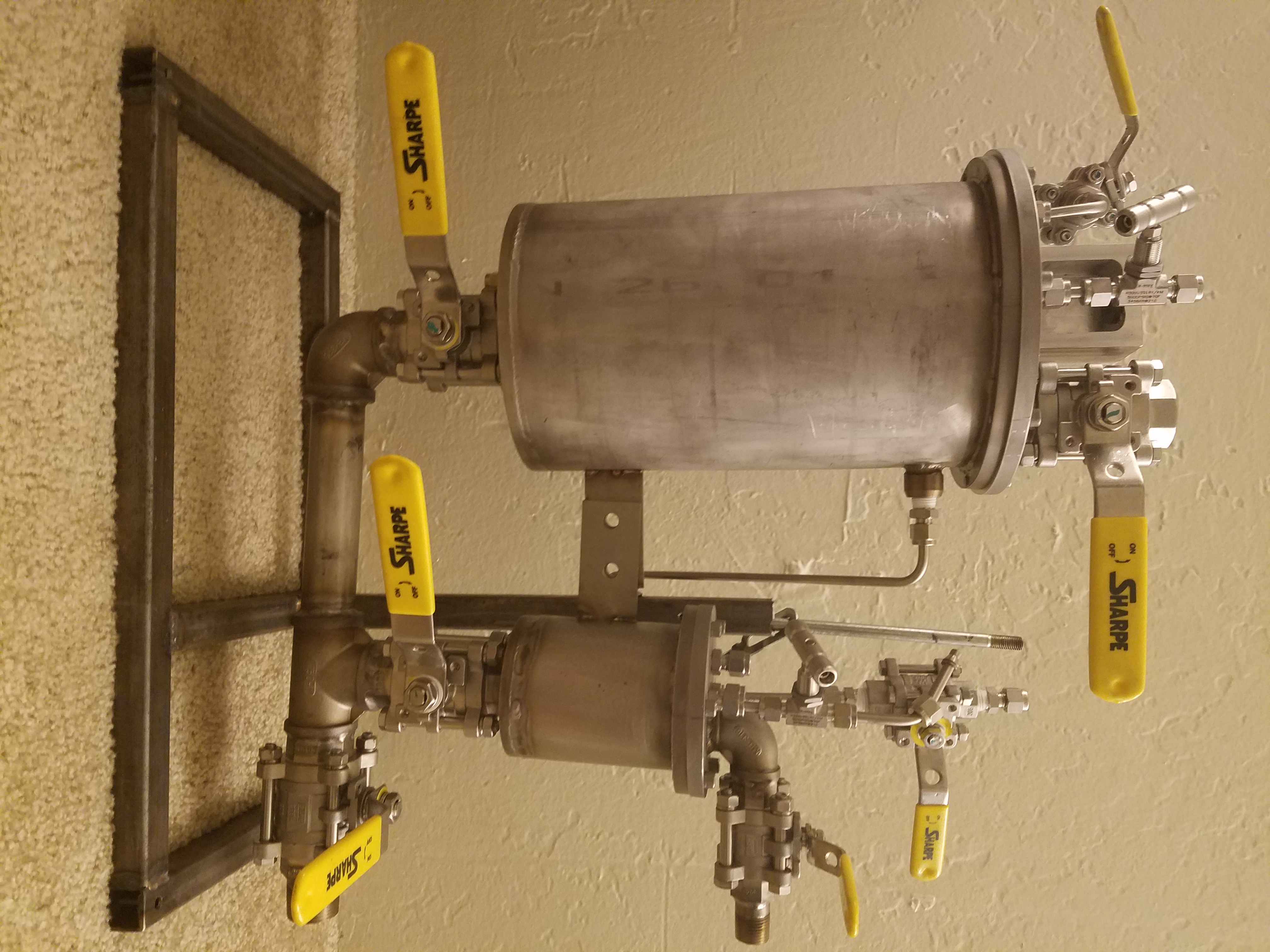
Before joining Ambercycle permanently I was asked to create a lab-scale reactor and filter system. At the time they needed it to fit inside a benchtop hood. The design, though compact, was very successful and I was offered a permanent position shortly afterwards.
After the machine shop was completed I immediately began constructing lab-scale reactors to study new processes.
Prior to building the Ambition pilot-scale reactor, the following lab-scale reactor was created to prove out the process:
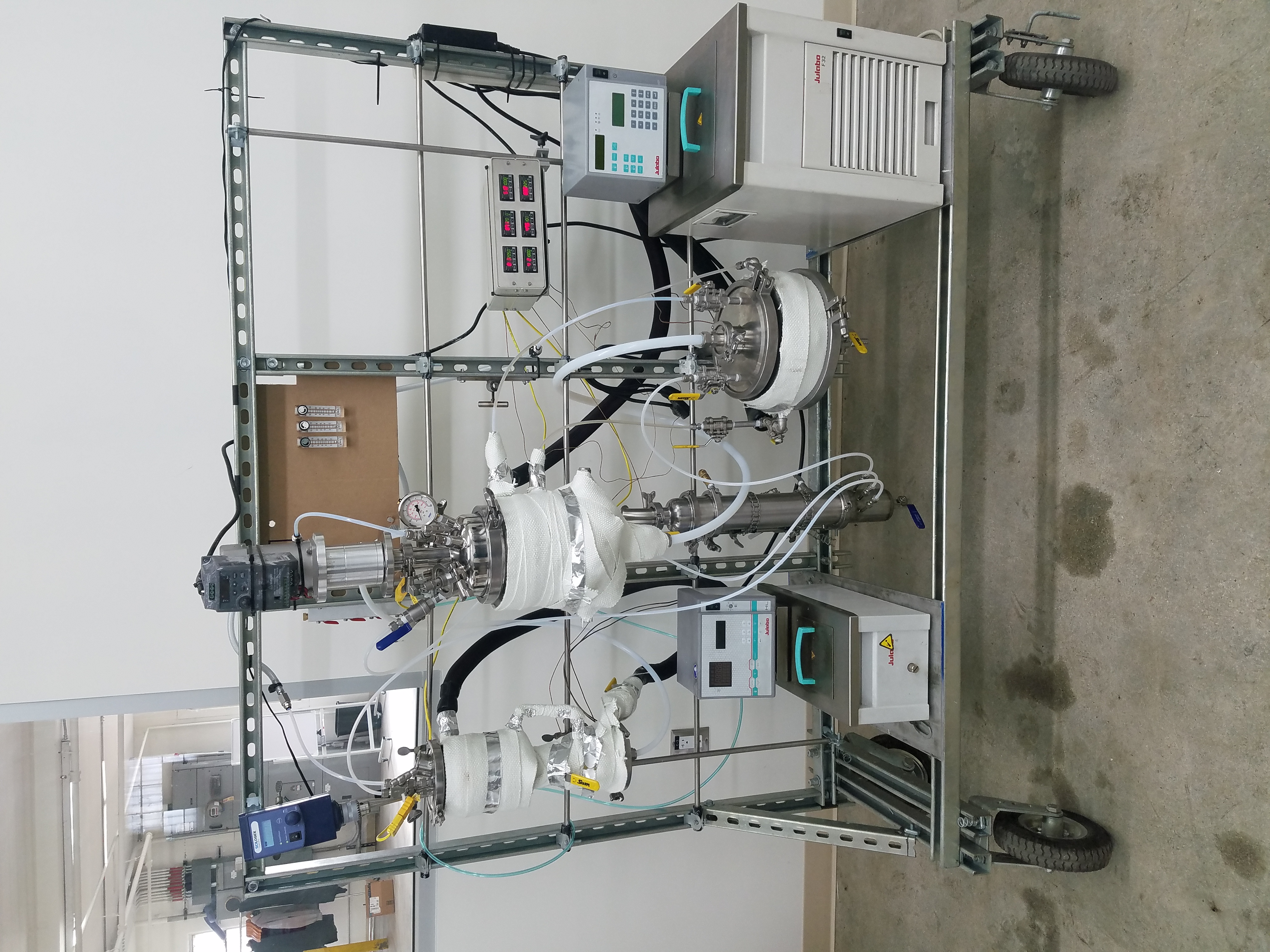
Tri-Clamp parts were leveraged as often as possible to speed up the assembly process and allow for fast changes to the design.
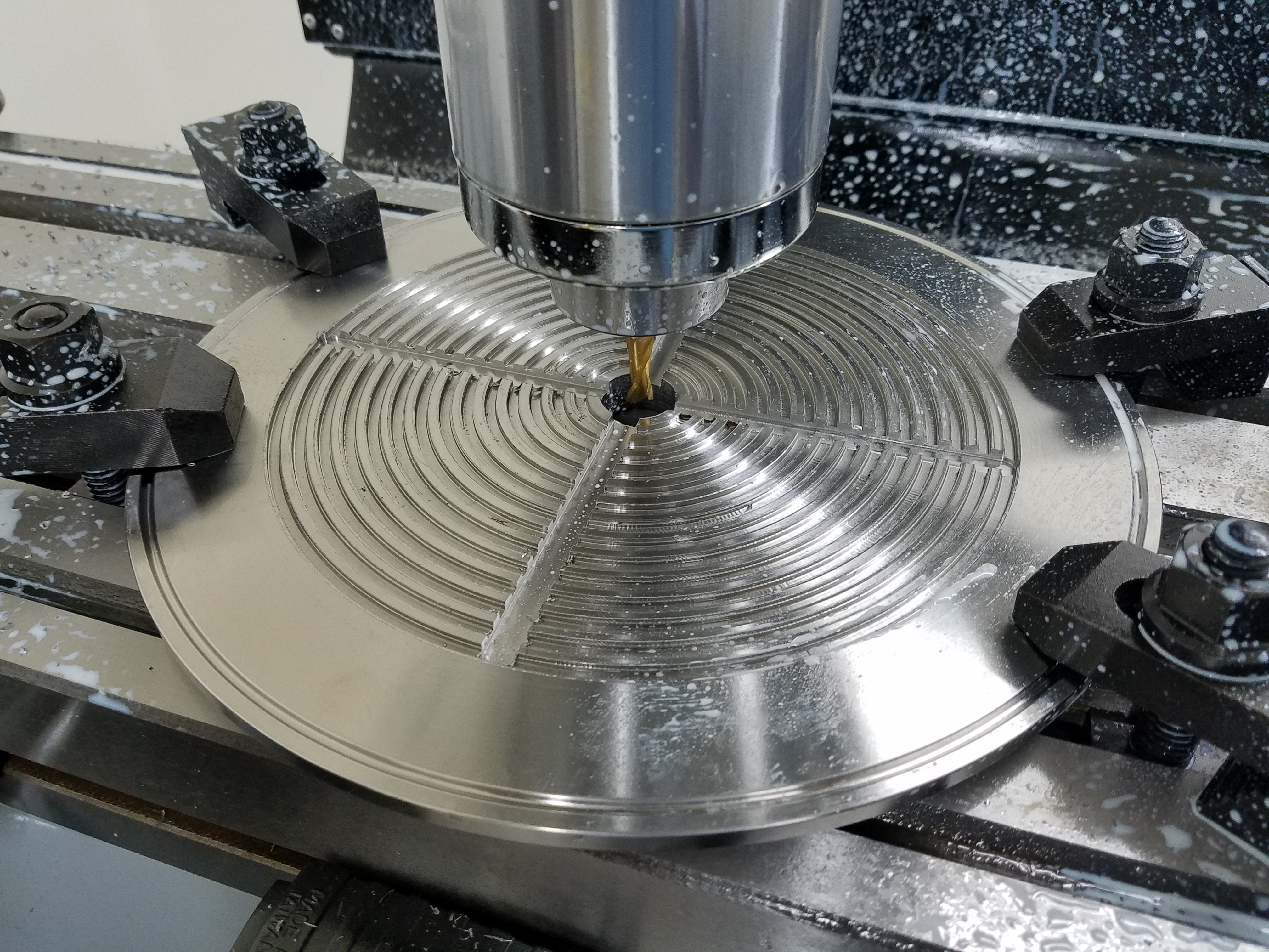
And when specific tri-clamp parts were not available, they were created by modifying tri-clamp caps.
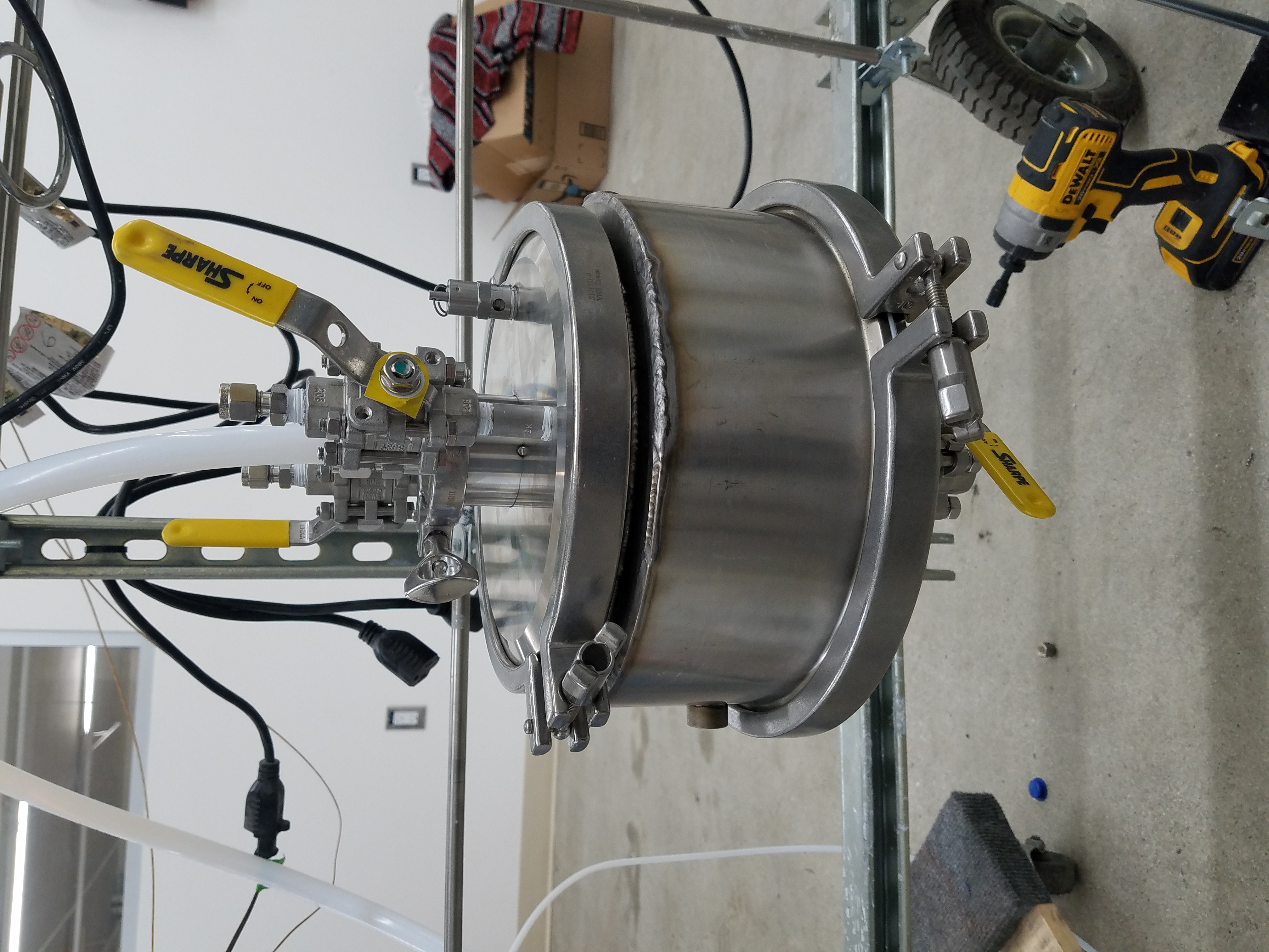
This filter was modified to have a hot-oil jacket, by using the 12in flange on to bottom an offset was also created that was used to hold the filters in place once assembled.
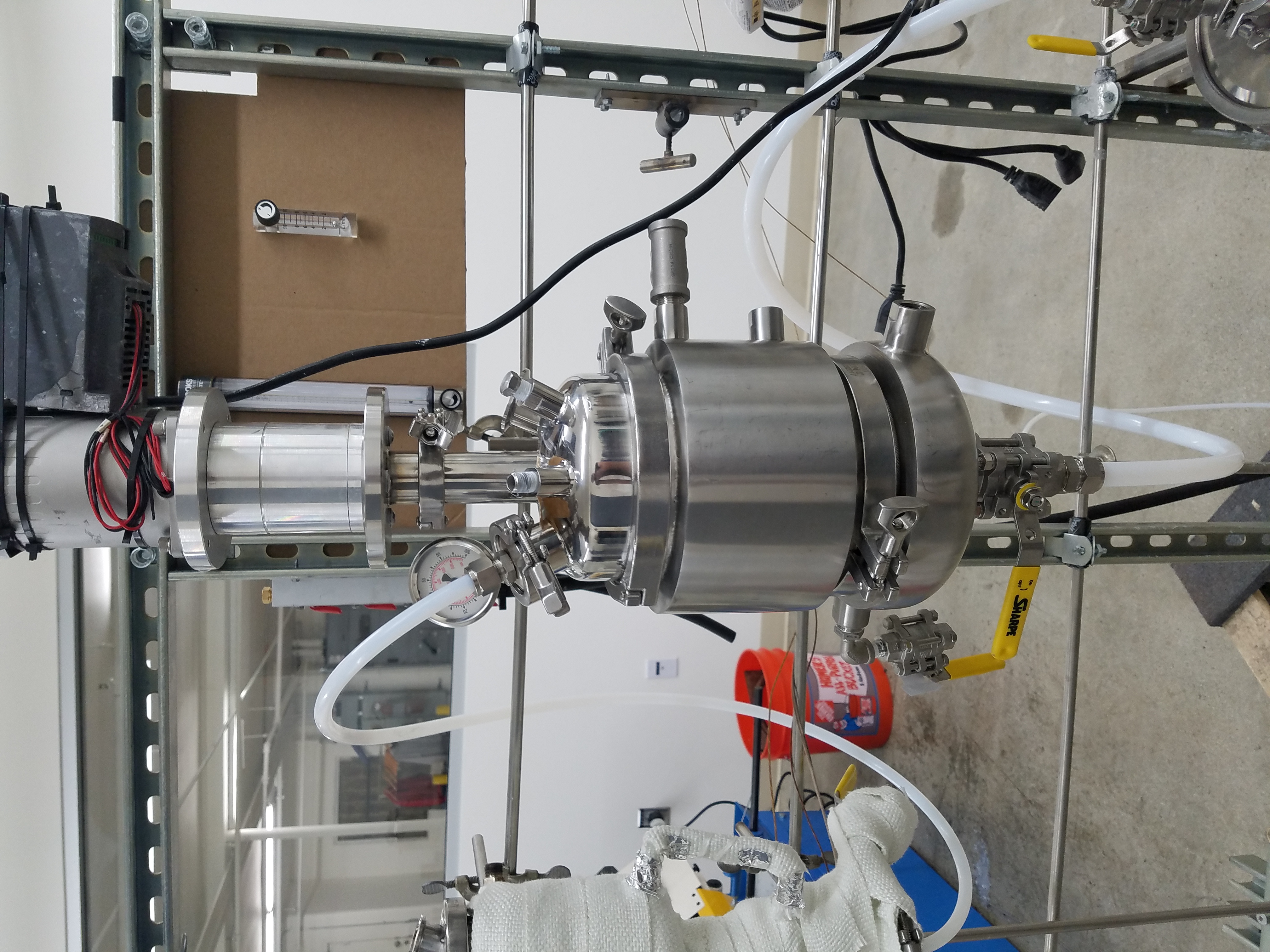
I was also able to source inexpensive VFD's and 3PH motors to create low-cost programmable stirring systems with high-torque.
Here again is the assemble reactor, this system was designed, built, and operational in only two weeks time.
Ambition
My first Pilot-Scale reactor was aptly named Ambition. The goal was to build a system around a Netuche filter that had been purchased used. Restoring the filter to operation was not without it's challenges, but we succeeded in putting this systems together in about three months. Because of the aggressive timeline, I had to create custom solutions where more favorable solutions would take too long to procure.
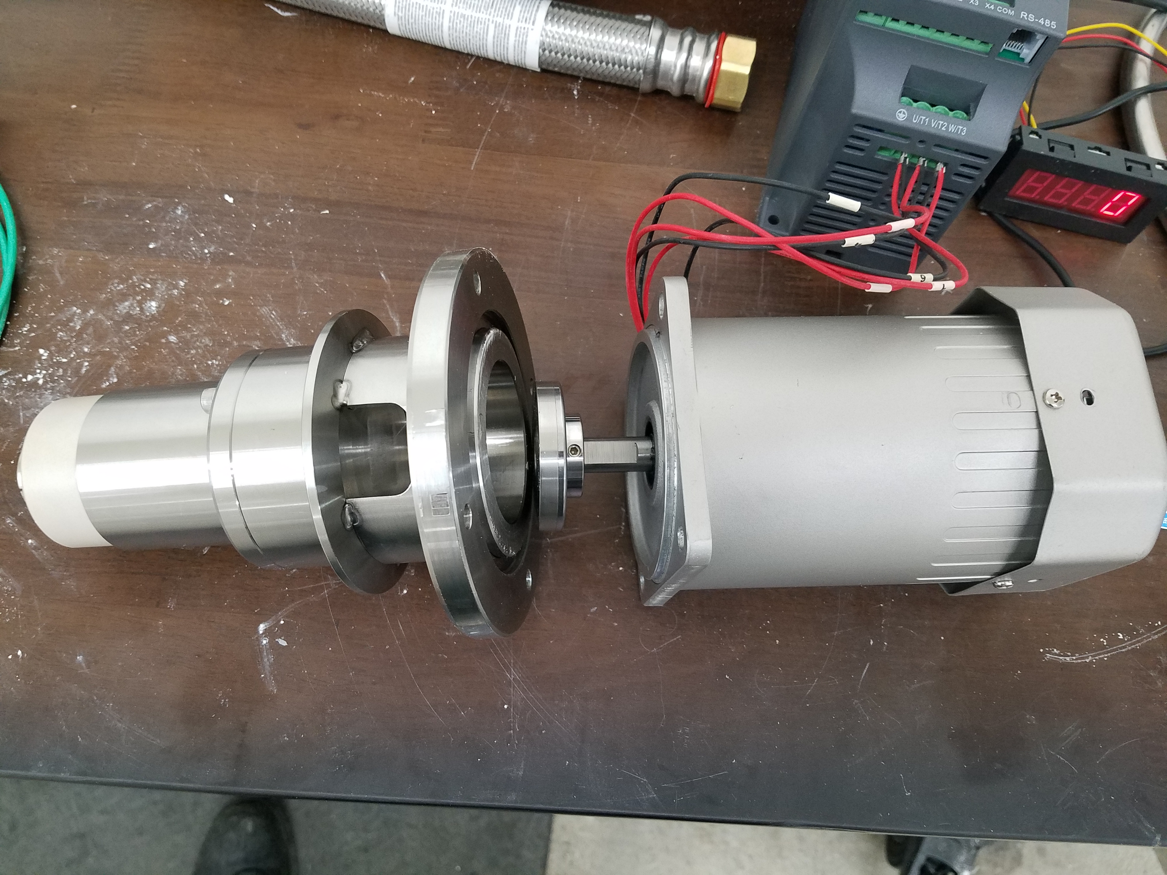
One of these custom solutions was a magnetically coupled stir-motor for the reactor. Because we were working with difficult solvents, traditional seals were not a favorable option. My solution was to machine this system and magnetically couple the shaft and motor through a very thin ~2mm sheet of SS316. This sheet was actually just a portion of a tri-clamp cap that had been thinned out in the middle. The stirring section was built using 316SS and featured a custom labyrinth seal and full ceramic bearings. It was a lot of work, but I was able to design, procure, machine, and assemble the whole system very quickly.
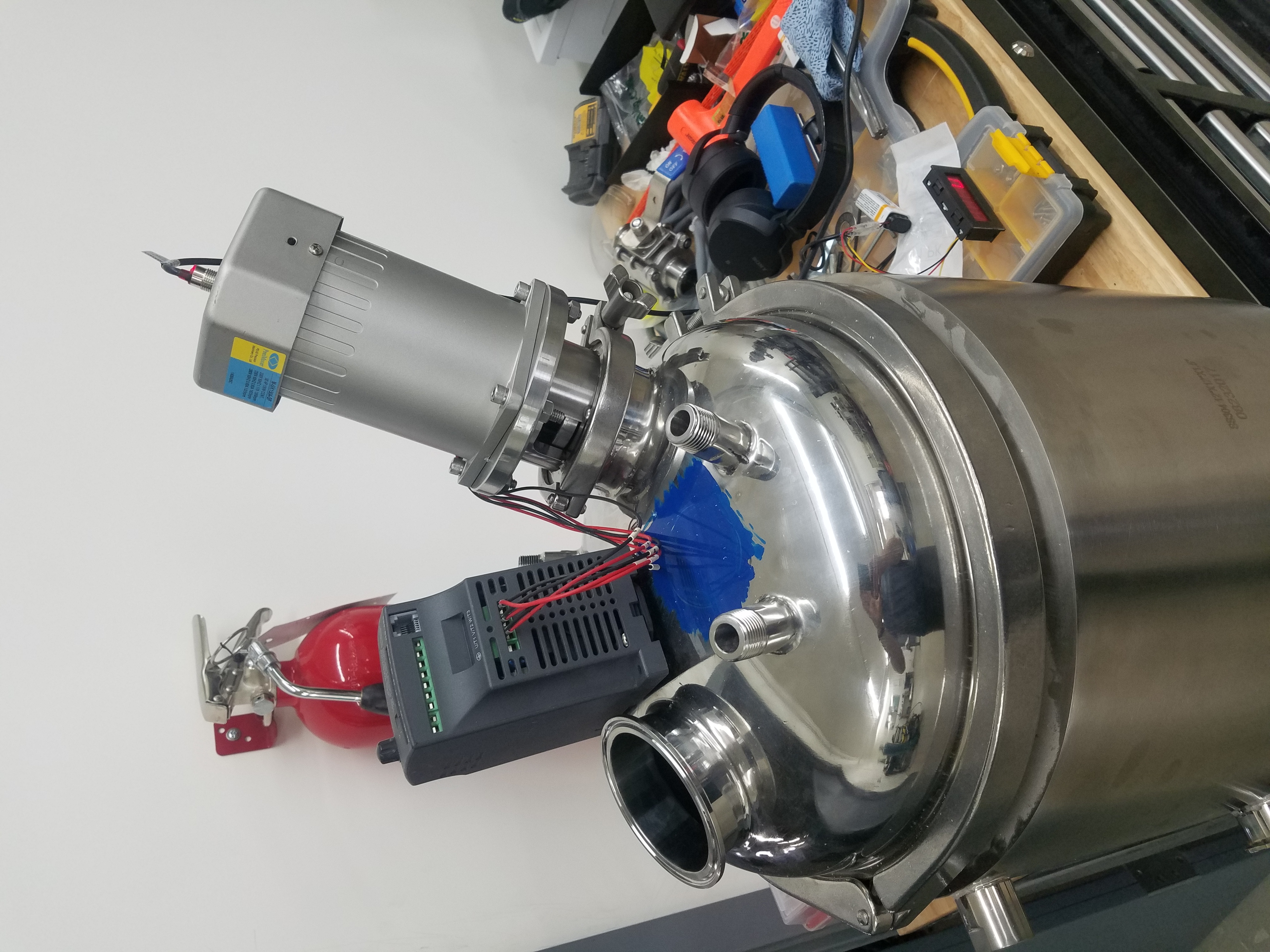
Here the system is shown with the VFD in place as well.
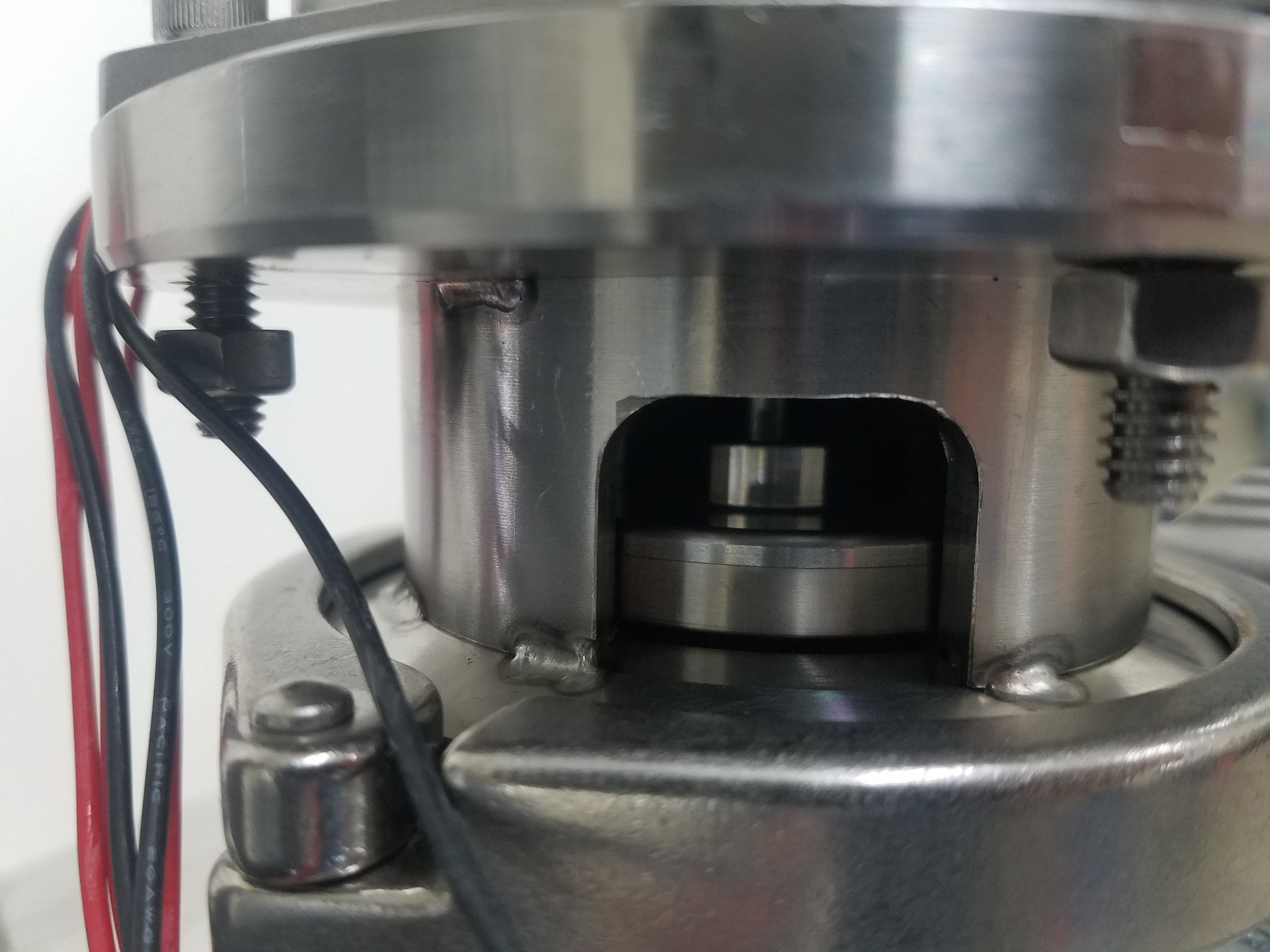
A close up shows how the system was coupled through a thinned out tri-clamp cap.
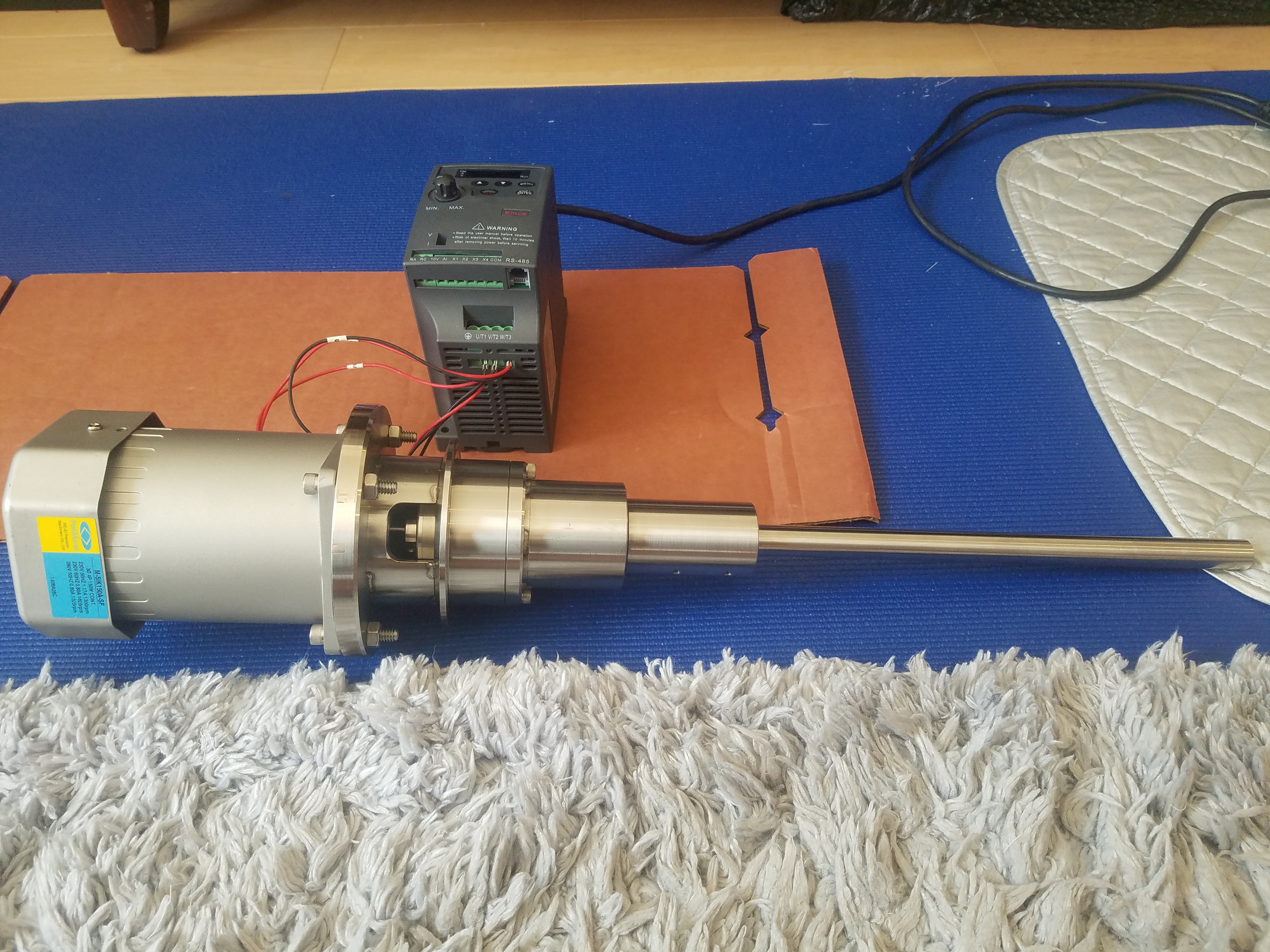
Here the system is shown with the shaft and labyrinth seal installed.
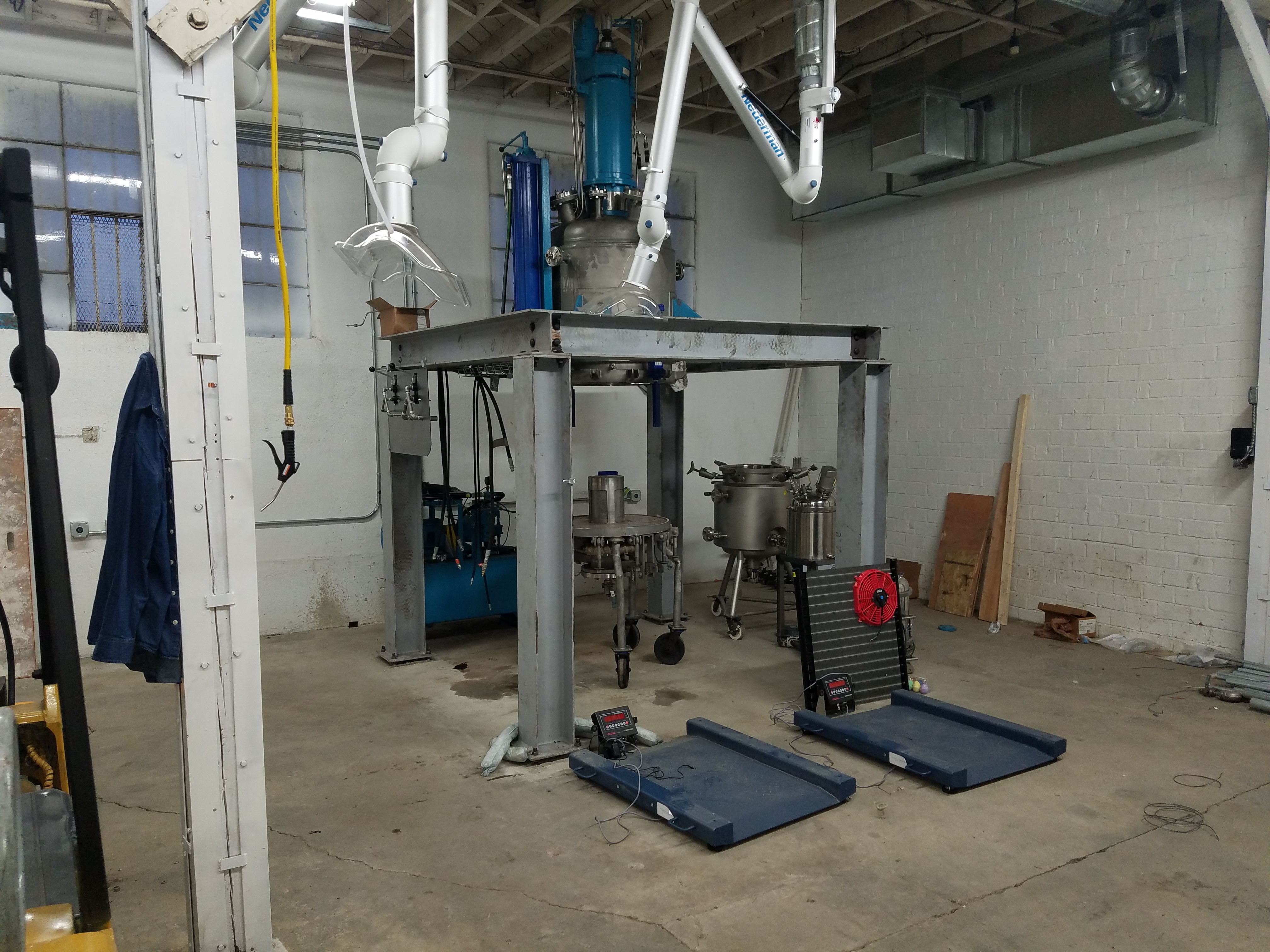
This is a very early view of Ambition just after the Netuche filter and platform were installed.
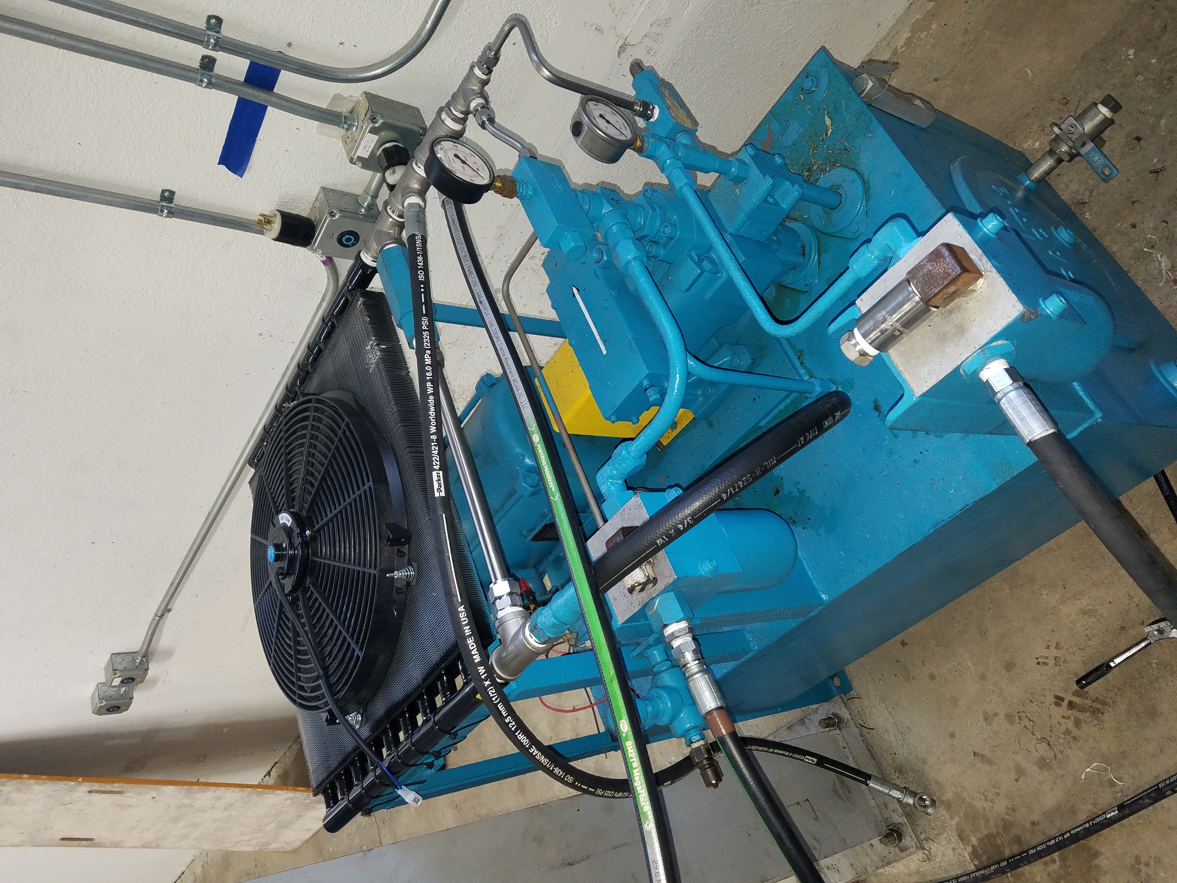
Since the project was on a rush schedule I had to refurbish the included hydraulic system with readily available parts.
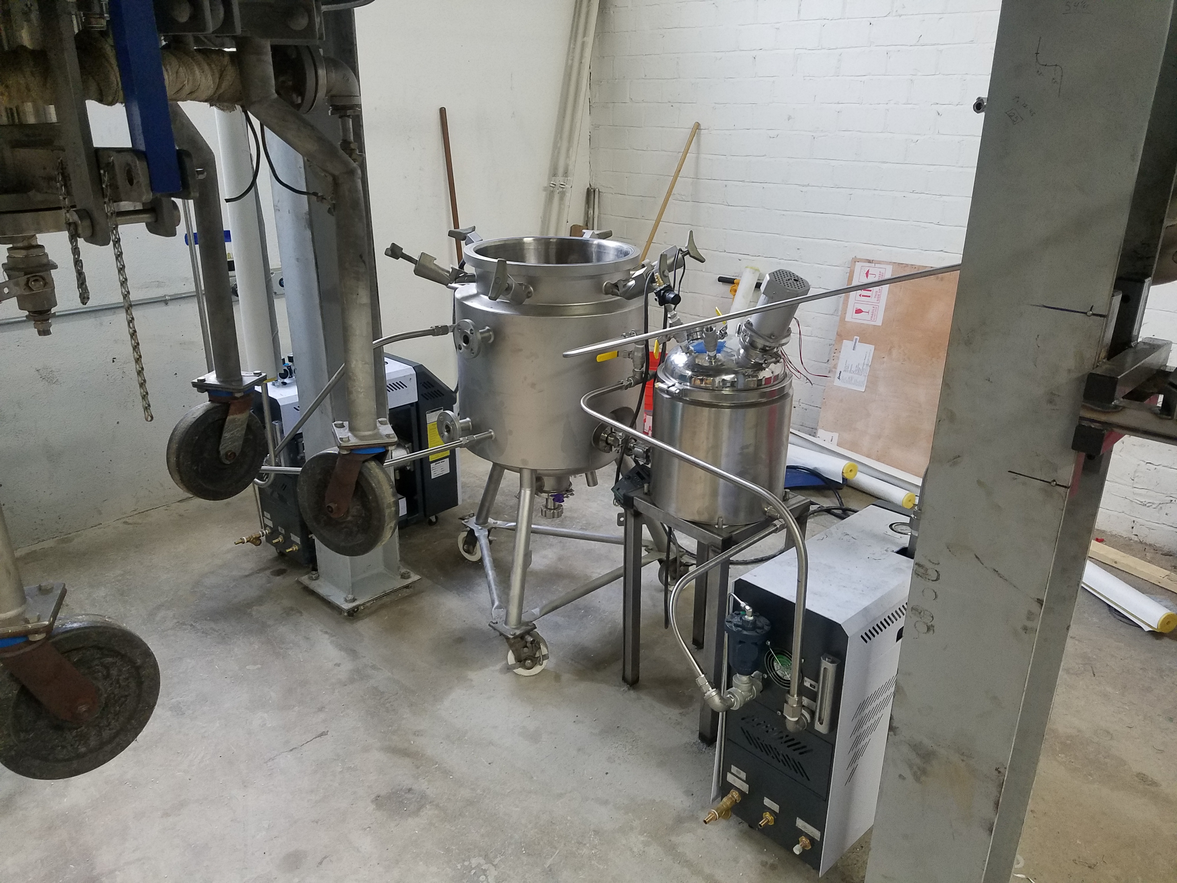
Here we have the reactor and crystallizer staged for installation.
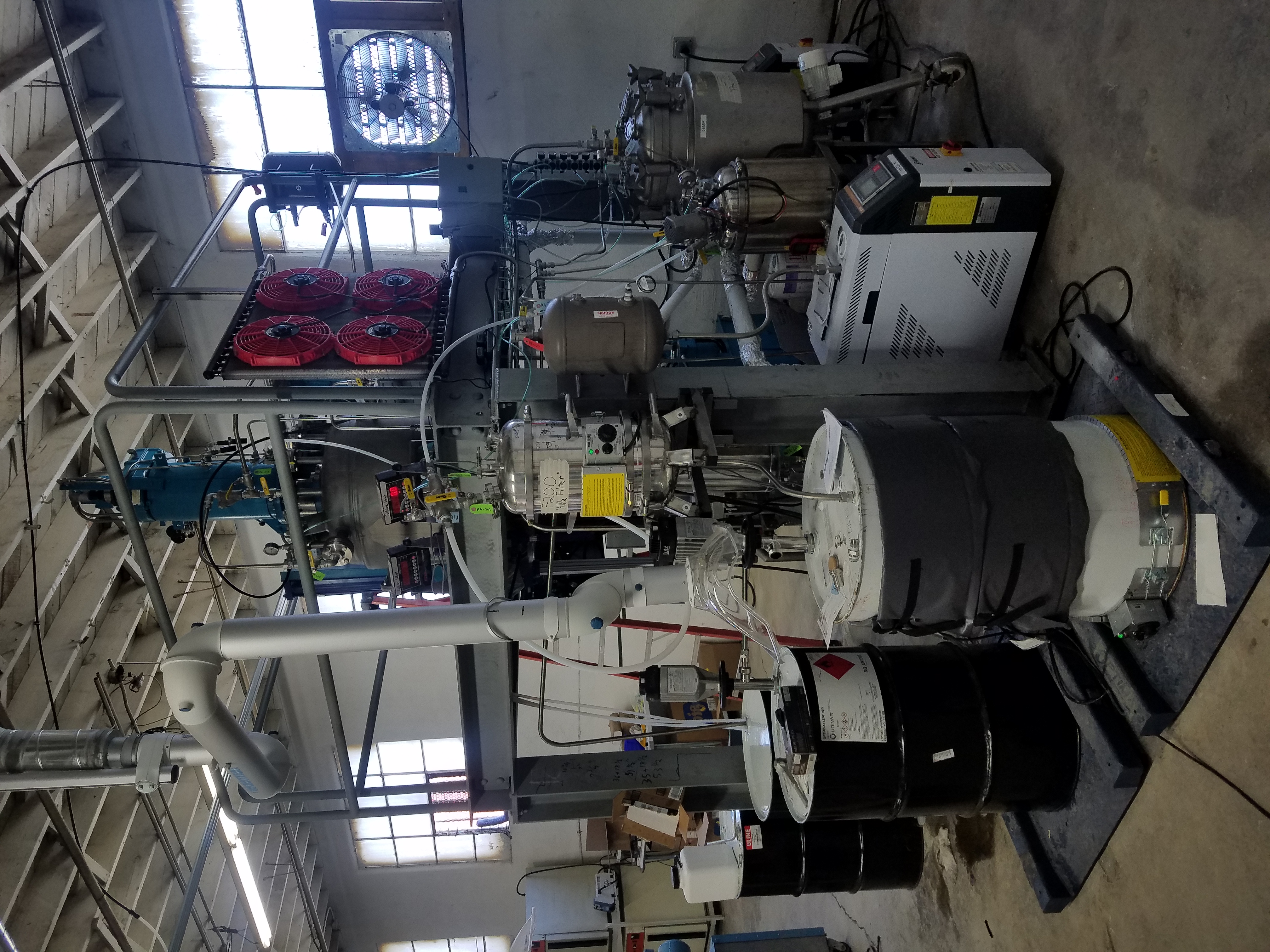
And here is the fully assembled system.
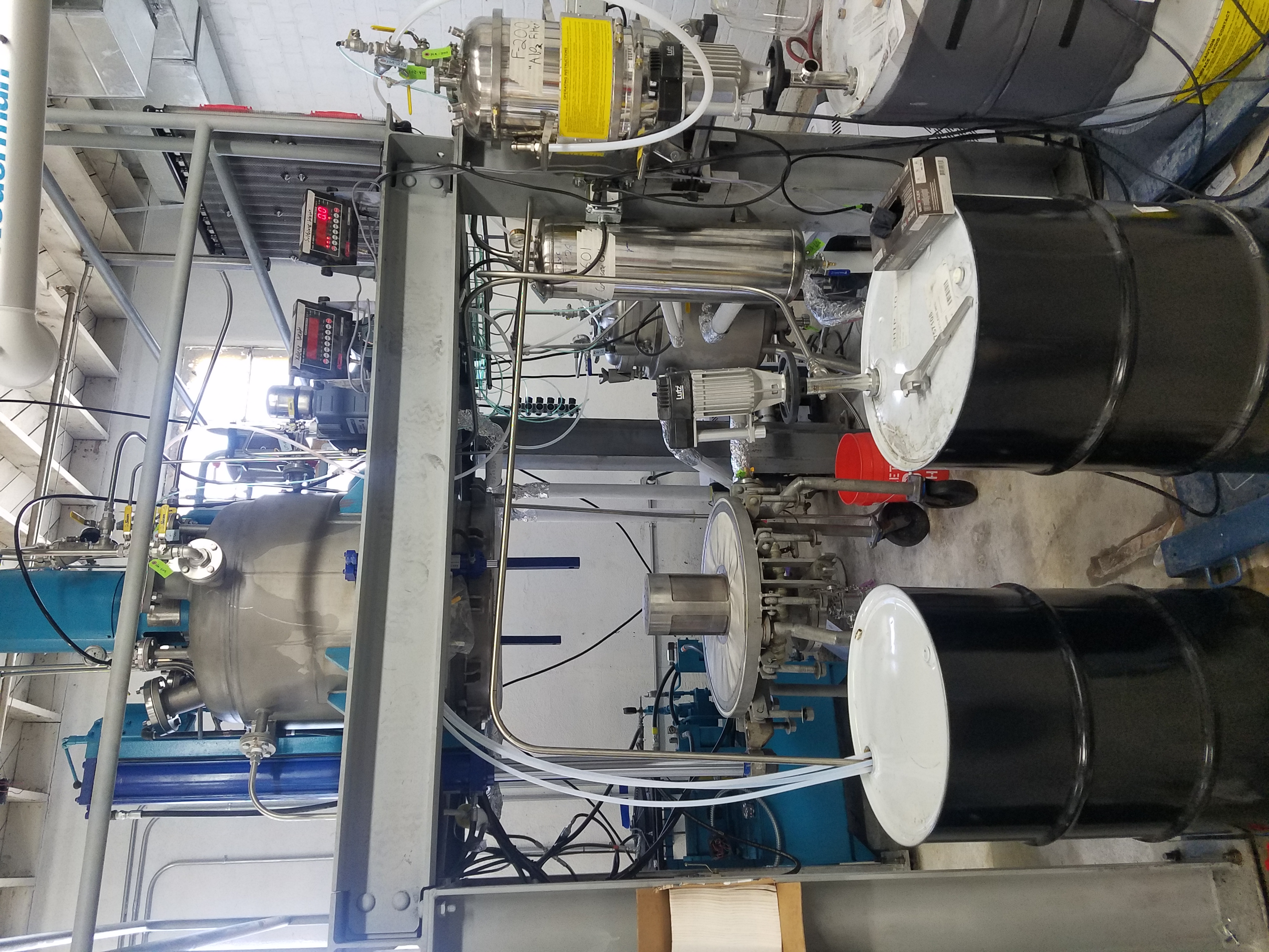
The Netuche filter is quite a nice system once operational.
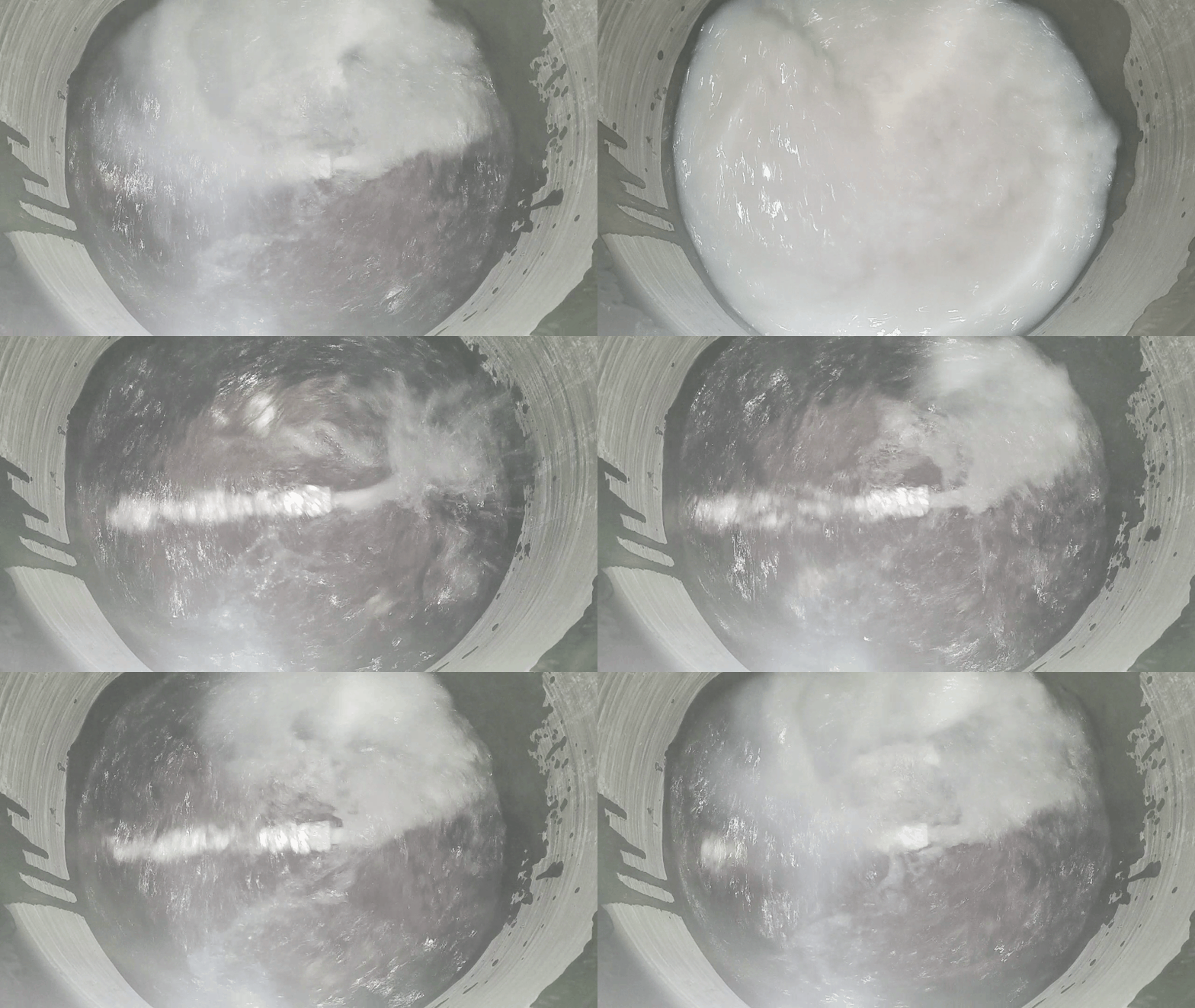
Another feature of our system was the crystallizer, I created and optmized a nozzle system to inject the dissolved polymer into an anti-solvent. The goal here is to create uniform crystals and avoid agglomerization so washing and drying are more efficient.
Solace
Shortly after completing and using the Ambition reactor to produce good product another chemistry was discovered that had obvious advantages over the chemistry used for Ambition. The advantages were so compelling that we immediately put Ambition on hold and began to design and create a pilot-scale reactor for the new chemistry. We called this project Solace because it was a more simple process im many ways. However the simplicity was not without it's challenges. The solvent used in Ambition did not produce any appreciable pressure at the temperatures we operated at. Solace on the other had would be operating at about 500 PSI and 400 degrees F. These operating conditions combined with the chemical compatibility of the solvent used meant that PTFE and the cost prohibitave FFKM were our only choices in non-metallic seat materials. In spite of these challenges Solace was operational within six months and from that point on was operating almost every day.
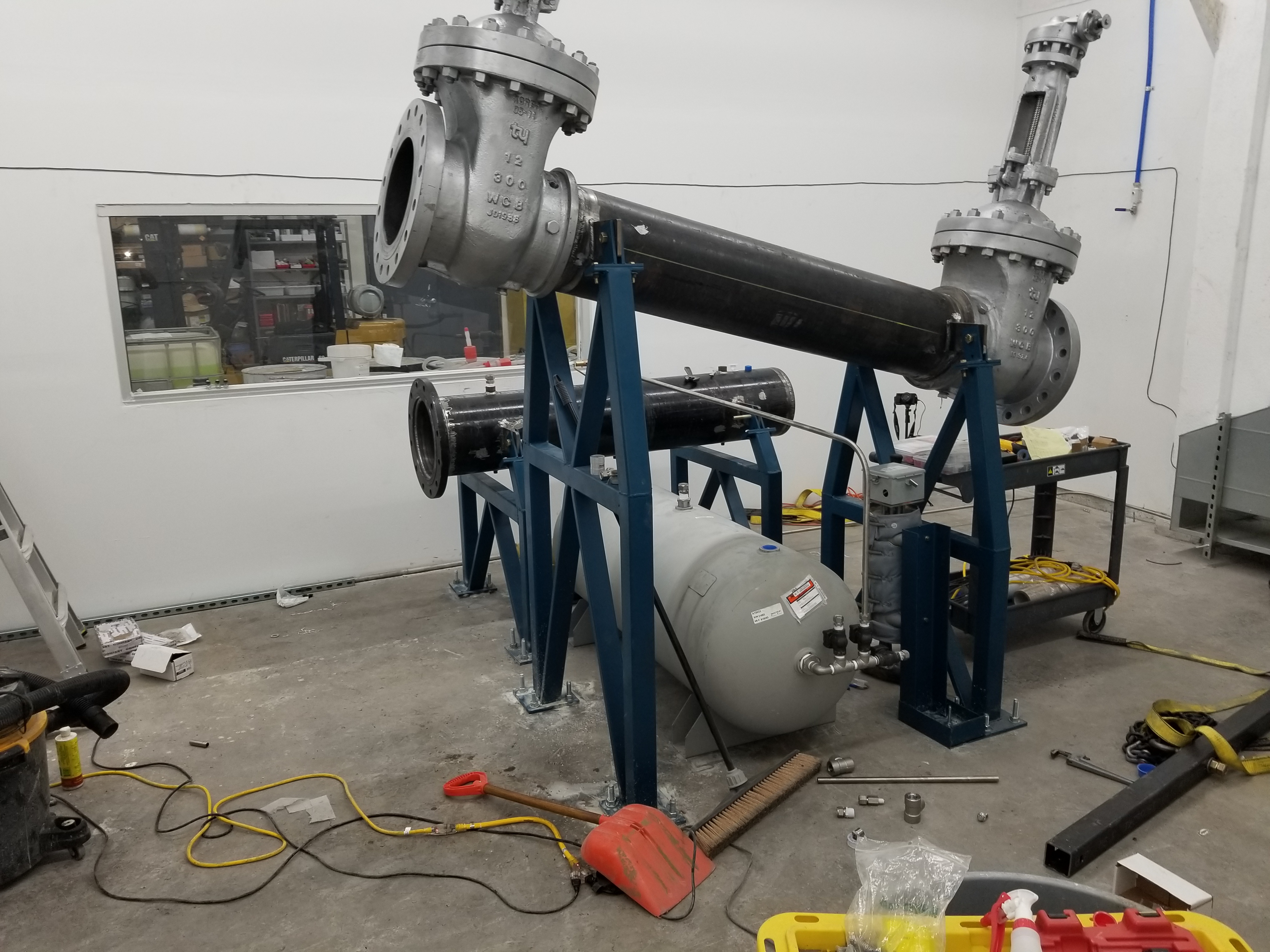
The valves used for Solace were wedge-gate valves with a metal to metal seal, this seal is imperfect so Nitrogen was fed into the central cavity of the valves at a slightly higher pressure than the process operated at. This prevented leaking of our porduct and solvent since the nitrogen was leaking in rather than the solvent leaking out, and the leak was small enough that process pressure was relatively unaffected.
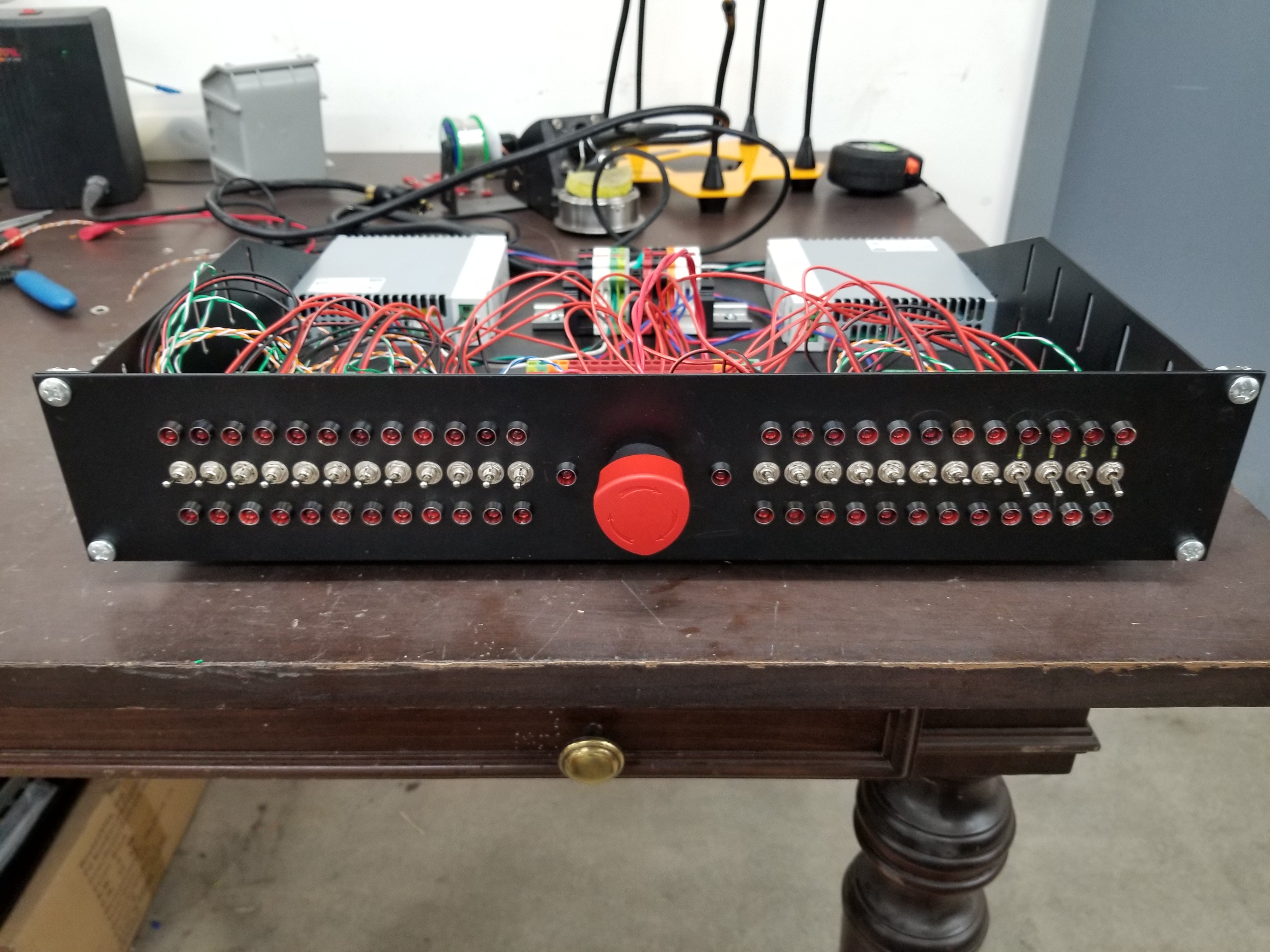
For safety reasons the entire system was contained in a closed off room with it own ventilation system. This required all valves to be automated. A simple switchboard with feedback from the valves was quickly assembled. Some interdependant valves were protected from user error through relay logic. Redundant power supplies were also employed to avoid loss of use.
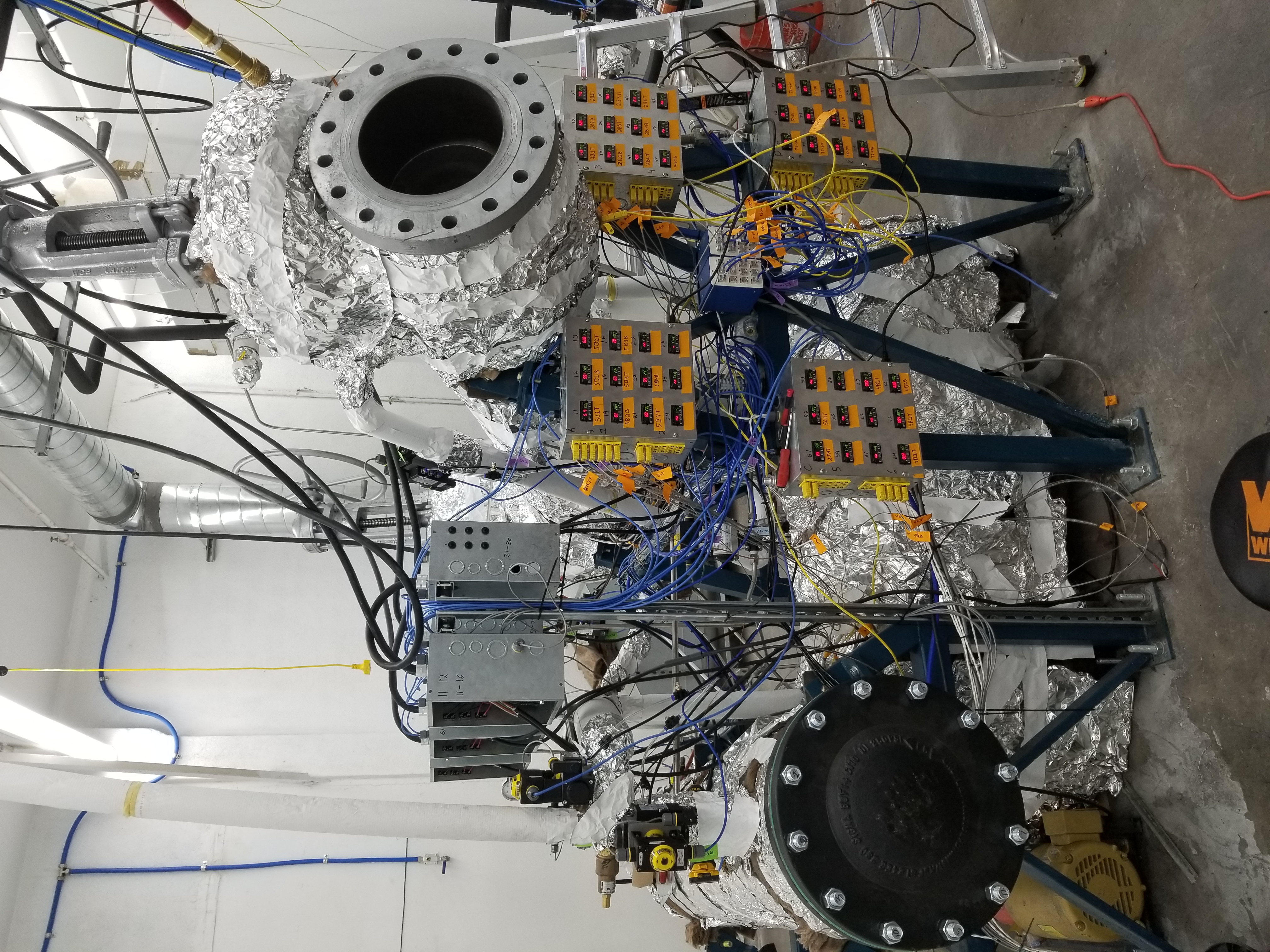
PID arrays were created using easily sorced enclosures and laser cut face plates. All PID's were connected to a computer via RS485 for monitoring, control, and logging.
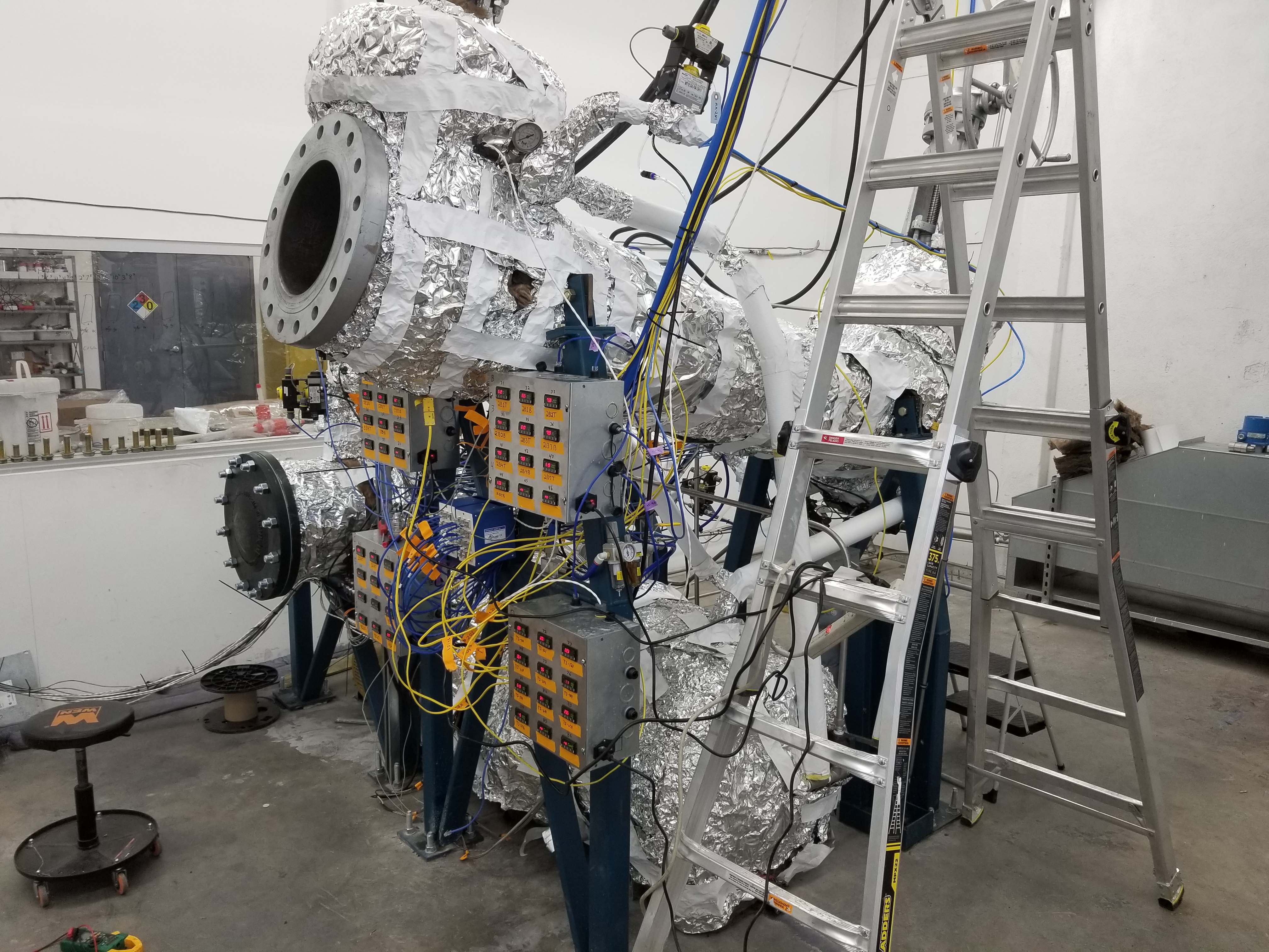
Here is another view of the system as it neared completion.
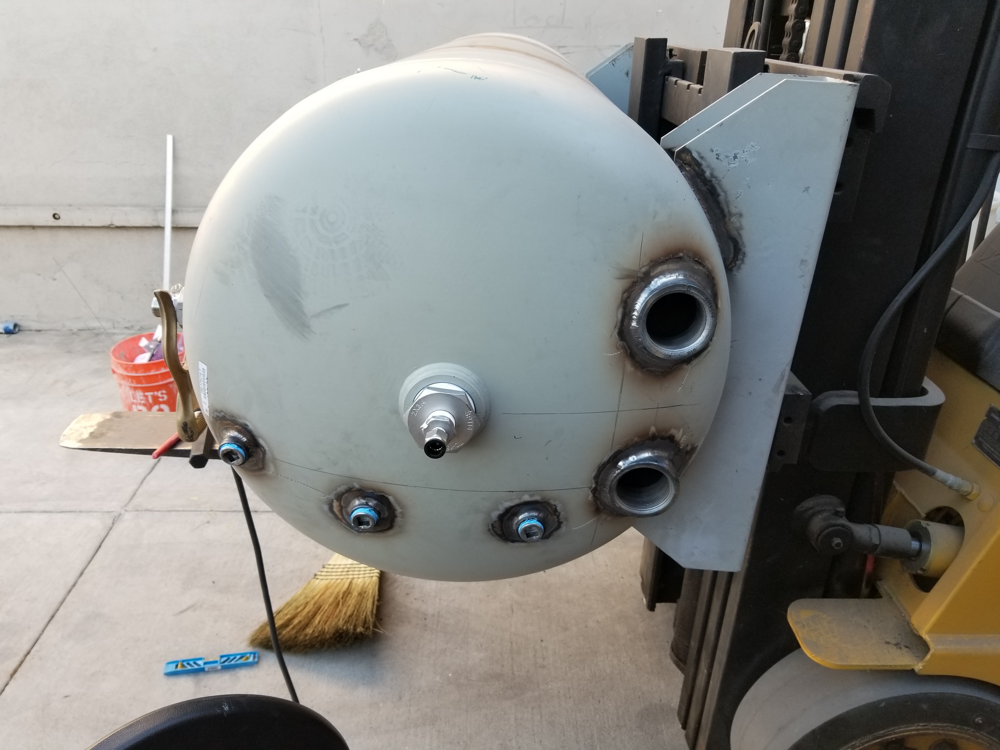
The solvent regeneration tank had to be modified to allow access for periodic cleaning, and so that larger immersion heaters could be installed.
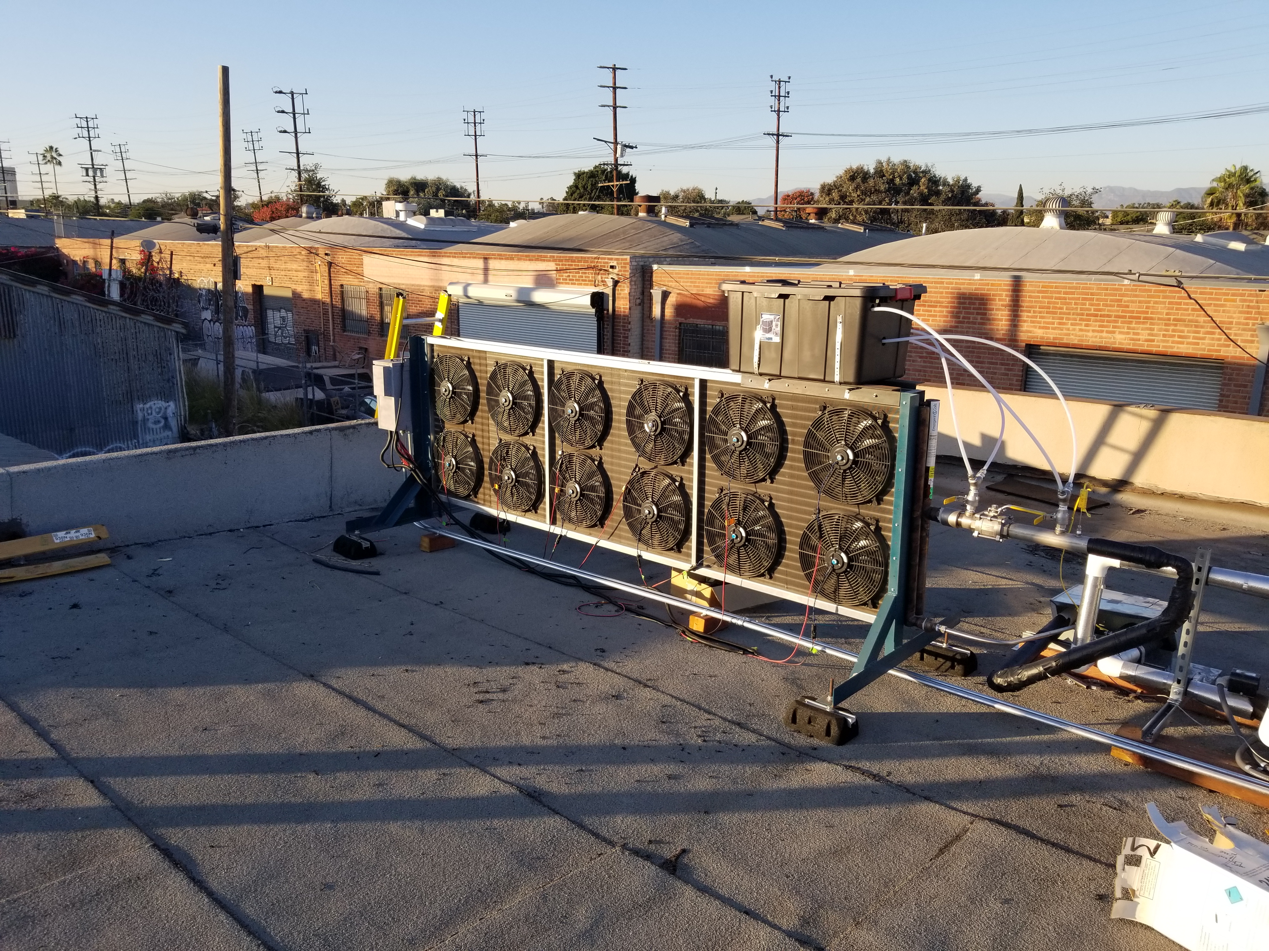
This is the primary condensing unit for Solace, it was oversized to handle bursts of vapor during crystallization, during solvent regeneration it easily rejected about 50KW of heat.
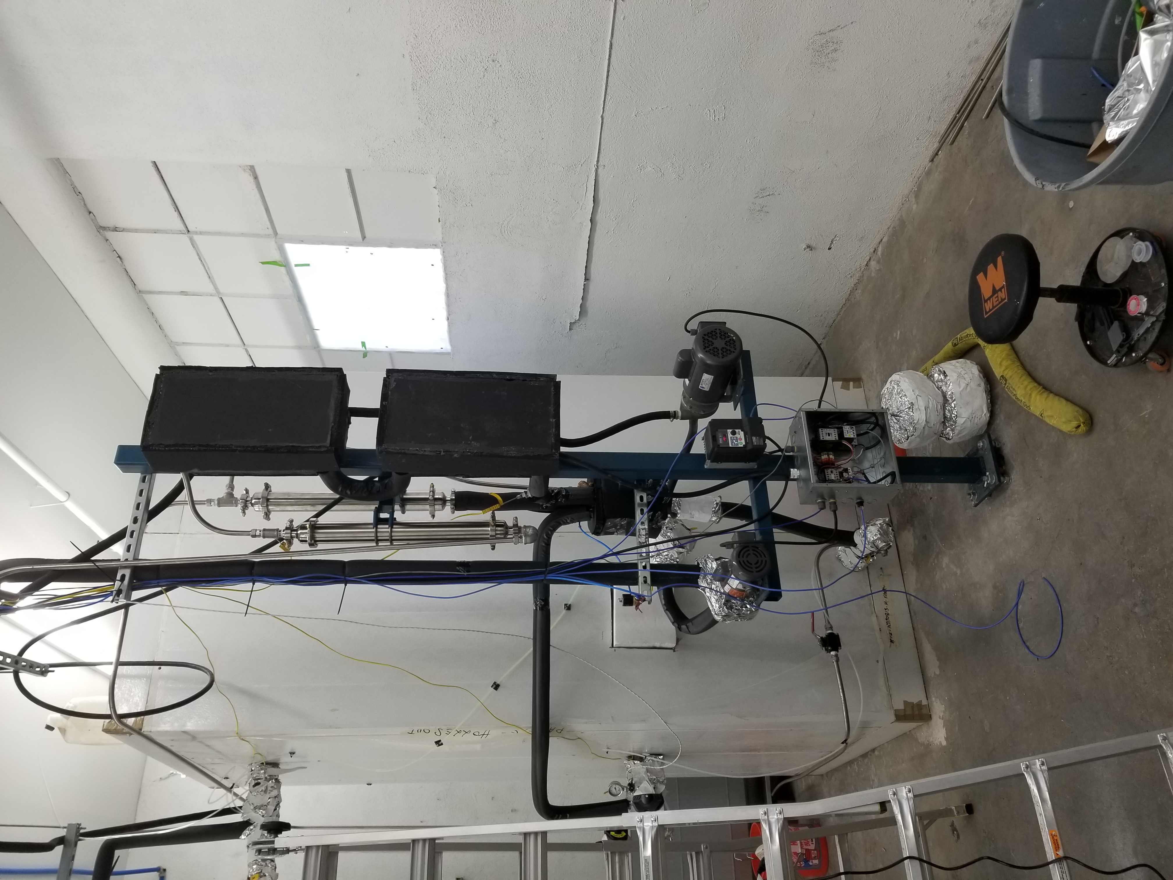
Our solvent was routinely purified via distillation and supercooled prior to returning to storage. These heat exchangers were the first attempt at supercooling, and while they worked fairly well they were difficult to implement prior to phase separation of the nitrogen gas (the gas would effectively reduce the surface area of the heat exchangers). Early on it was apparent that a new solution was necessary, and this was quickly created and implemented as shown below.
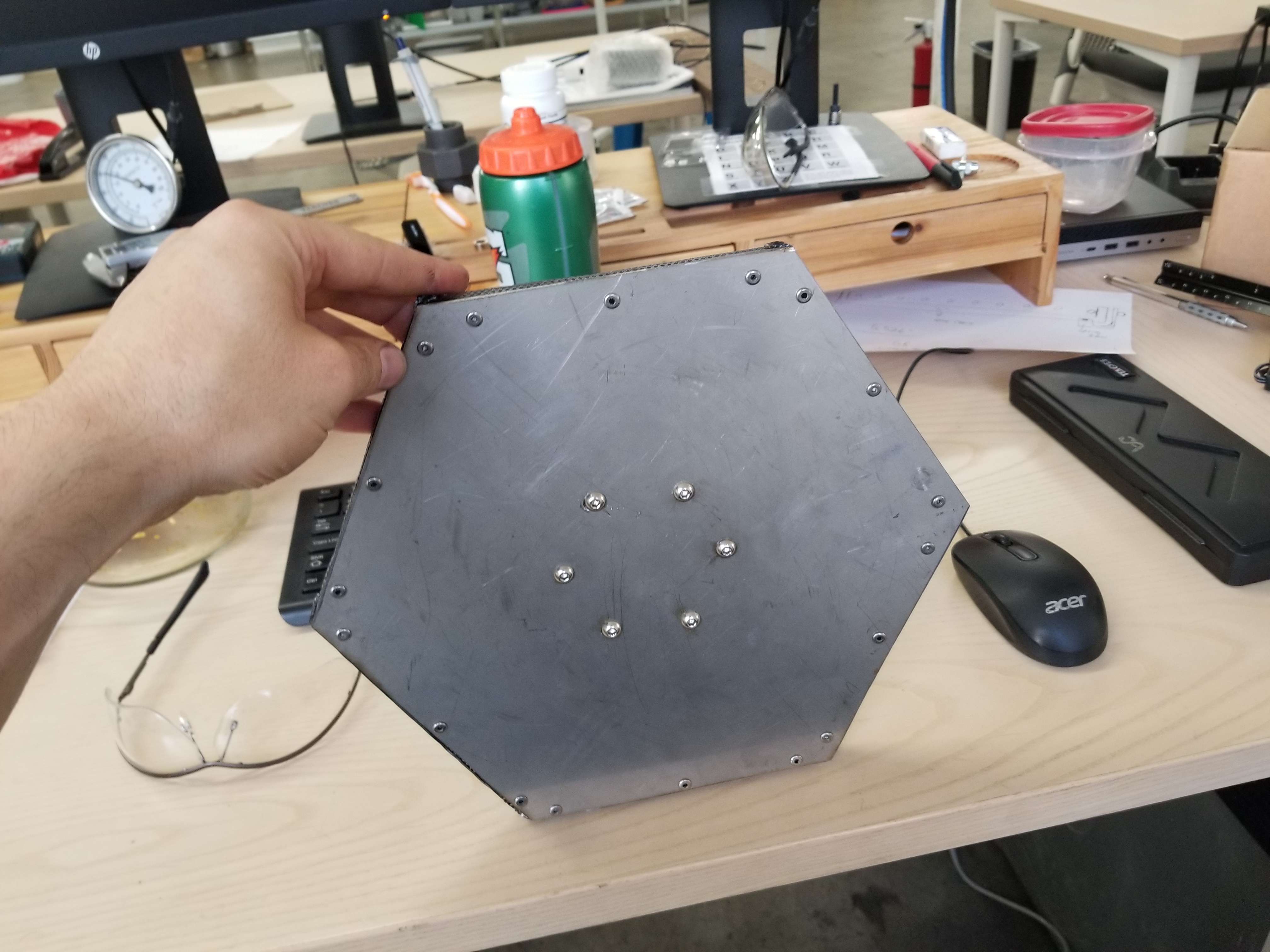
In spite of the oversized condenser coil solvent losses were still high since phase separation was happening at elevated temperatures. The phase separation was necessary because nitrogen was present in our system as it was used to purge oxygen, move things around, and backbleed the gate valves. The solution was a gas/liquid heat exchanger and phase separator in one. This was the first iteration of the bubbler component of the system (bottom view).
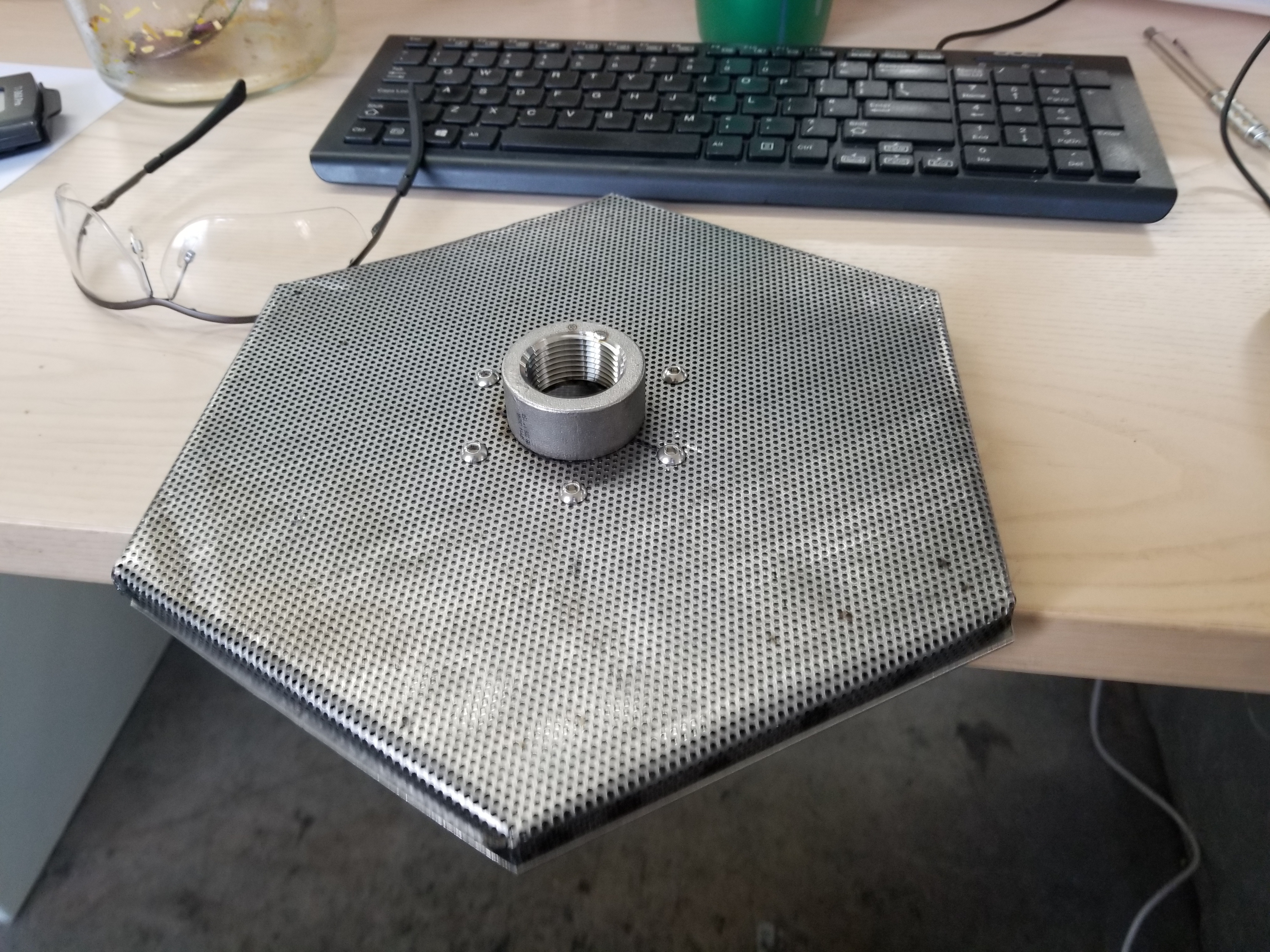
And here is a top view of the 1st iteration bubbler component. Testing was done using water to determine if the bubbles remained small or coalesced, this iteration performed poorly. The 2nd iteration was howerver a success.
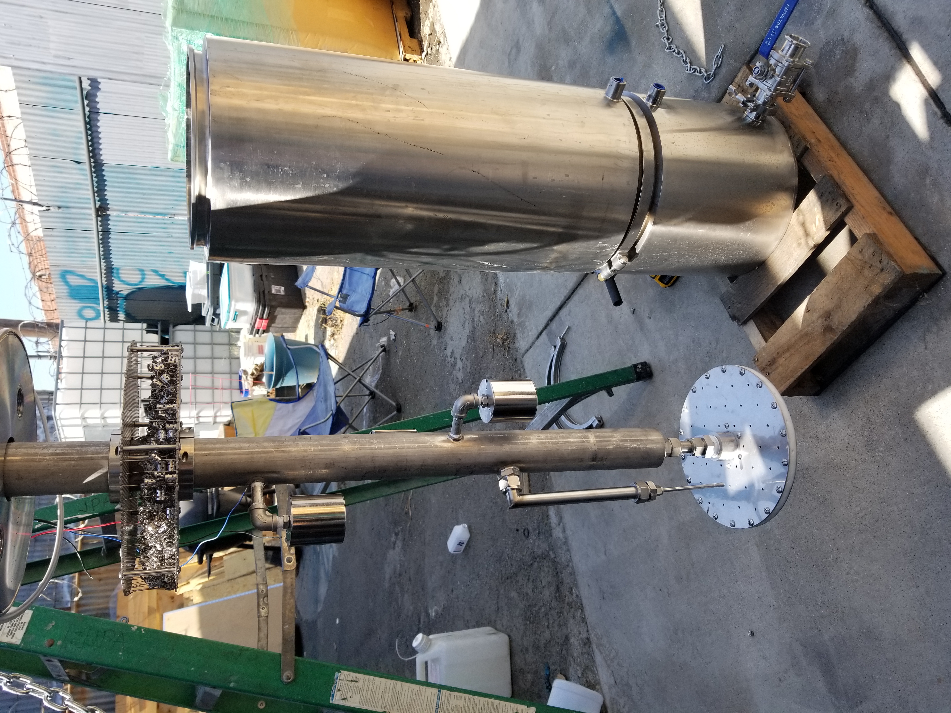
Here you can see a much improved version of the bubbler. In this system supercooled liquid solvent was maintained within a specific range of volume using level indicators and valves driven by relay logic. The solvent/nitrogen mixture was bubbled through the supercooled liquid and the nitrogen was allowed to escape while the solvent vapor condensed and stayed in the solution. Raschig rings were added as a final obstacle for the solvent.
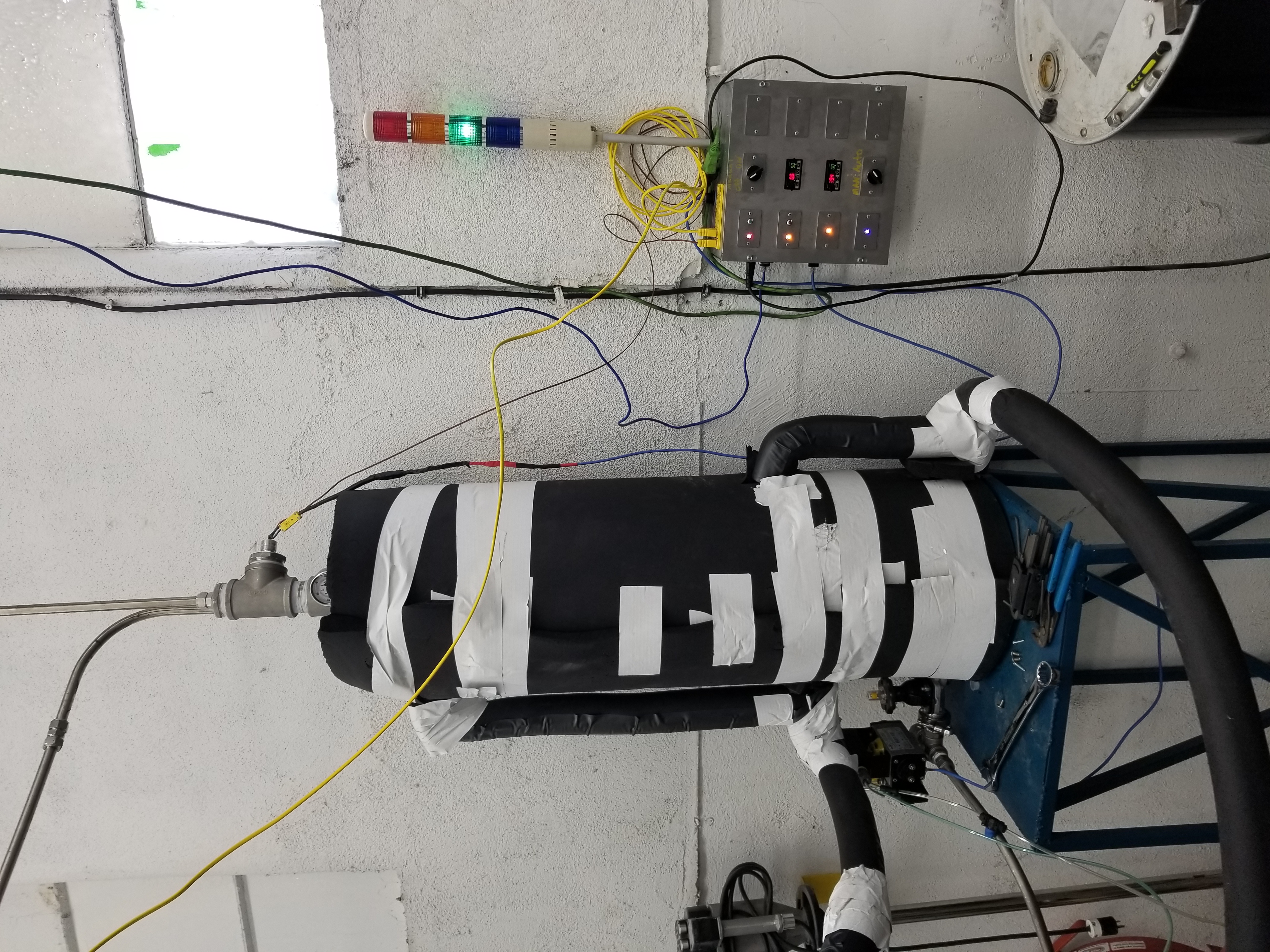
Here the heat exchanger / phase separator is installed and functional. This system was extremely successful and solvent losses were very minimal.